Electric actuator technology prospers in production fields
President Obama’s Climate Action Plan has a goal to cut methane emissions from the oil and gas industry by 40% to 45% from 2012 levels by 2025. This has led to new regulations that require widescale pump retrofitting.
 Methane is a major component of natural gas, and is also a greenhouse gas that is 25 times more likely to contribute to global warming than carbon monoxide. The U.S. Environmental Protection Agency (EPA) estimates that 30% of methane emissions come from the oil and gas industry.
When breaking down where these methane emissions come from, pneumatic devices are considered one of the top contributors, especially with natural gas production. Pneumatic devices in gas extraction are designed to vent methane into the atmosphere as a part of normal operations. This vent or "bleed" of natural gas not only contributes to poor air quality, but also hurts the oil and gas producers by not capturing the value of this gas as a sellable commodity.
There are two basic types of pneumatic devices that bleed methane to the atmosphere: controllers and valve actuators. While controllers bleed gas continuously, valve actuators bleed gas only when the valve is stroked open and closed. Pneumatic devices typically work as described below:
- High pressure gas is controlled by a pressure regulator valve to a constant pneumatic gas supply pressure
- Mechanical process measuring devices further regulate the supply gas pressure to a weak pneumatic signal depending on the process measurement:
- High to low level, pressure, temperature, and flow rate.
- The weak pneumatic signal flows into a controller which, through a precision set of nozzles and orifices, directs the pneumatic supply gas to or from the valve actuator.
- When supply gas is routed to the actuator, the diaphragm pushes the valve plug open or closed
- When supply gas is vented, an opposing spring pushes the diaphragm back, closing or opening the valve.
- The weak control signal is often vented continuously (bled) to the atmosphere.
- The strong signal is vented intermittently – only when the valve opens or closes.
- In addition to the controller bleed rates, leaks and malfunctions must be considered as a potential gas-venting source. Leaks from the various tube joints or other points within the tubing network are possible due to worn gaskets or loose fittings. Malfunctions within the controller are possible because of foreign material blocking the nozzle, creating a continuous bleed or excess moisture in the supply gas, which can cause nozzle corrosion.
The size of the problem these pneumatic devices create is debatable. Several studies have been done on the number of pneumatic devices installed and the amount of methane they bleed or vent. For example, the University of Texas at Austin published Measurements of Methane Emissions at Natural Gas Production Sites in the United States (David Allen et al.) that concluded the amount of methane released is more than what the original EPA estimate suggests. Another study by the Oklahoma Independent Petroleum Association (Pneumatic Controller Emissions from a Sample of 172 Production Facilities, Nov.2014) concludes the emissions are less that the EPA findings. Regardless of the outcome, these devices still vent methane to the atmosphere.
 The good news is that programs such as the EPA’s Natural Gas Star Program encourages and facilitates voluntary reduction of methane emissions. One of the historic solutions by the program is the use of lower-bleed pneumatic controllers. A low-bleed controller is defined as having a bleed rate of 6 cu ft/hr or less, which can reduce the emission up to 90%. The issue is that many applications are not suitable for this technology due to higher needed pressures or faster reaction times. In addition, they still vent-even if the amount is reduced.
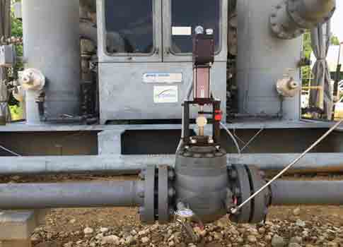
A more current and growing solution is the use of electric actuators to move the valve, eliminating the use of gas altogether. For most production sites, the electric actuators must be able to handle the forces required by the process and be able to react quickly to process changes with a 100% continuous duty cycle. In addition they must run on low dc voltage as solar-powered batteries are a common power supply for remote well sites.
Unfortunately, many believe that electric actuators are not suitable for the production field. The misconceptions are due to the limited capability of traditional electric actuators. A typical traditional actuator uses a small dc motor with a gear train to increase the output torque. It then adds a linear thrust unit such an acme screw to move the valve. The challenge is keeping the motor small enough to run on low current while providing enough force and speed to handle the application The use of a gear train slows the actuator down too much to handle to process changes. Another challenge at remote well sites is how to deal with power drops when batteries drain due to issues such as overcast weather.
A new approach that is being rapidly adapted is the use of an electric actuator that uses a servomotor integrated with a roller screw instead of a gear train and acme screw. Servomotors are up to 90% efficient, providing more torque than a standard motor without drawing additional current. They also include built-in feedback so the position of the valve is always known. Using a roller screw integrated within the servomotor provides a means to directly convert the motor’s rotary energy to a linear force, eliminating the inefficient gear train. Powered by 12 to 24 V dc, the electronics can monitor the bus voltage and safely close the valve at a predetermined value if battery drain occurs. The result is an electric actuator capable of the same or better performance offered by high bleed and low bleed pneumatic systems.
With the elimination of the pneumatic devices (controller, regulator, and actuator), an electronic controller must be used to control the electric actuator. In most cases, this comes from an already in place programmable logic controller or remote terminal unit via an analog signal to the electric actuator. This creates the more common electronic process control system used in other oil & gas process areas such as gas processing plants and refineries.
Electric actuation has been successful in: separator control, vapor recovery units, compressor suction control, gas injection, and plunger lifts.
As oil and gas producers continue to look for technologies to comply with new government mandates, targeting pneumatic devices could be one of the best places to make a significant impact. Switching to electric actuation not only solves the emission problem, but it also has the added benefit of improved control, reduced maintenance, and added process information.
Barb Boynton is a business development manager for Curtiss-Wright/Exlar Actuator Solutions. She has more than 30 years of experience in the process control industry. Edited by Eric R. Eissler, editor-in-chief, Oil & Gas Engineering, eeissler@cfemedia.com.
Do you have experience and expertise with the topics mentioned in this content? You should consider contributing to our CFE Media editorial team and getting the recognition you and your company deserve. Click here to start this process.