Three-dimensional (3D) imaging can be used to verify rope and cable quality to measure pitch length and diameter, and identify rope surface damage and type of wear, with accuracy surpassing current methods, to enhance safety. See photos.
Three-dimensional (3D) imaging can verify rope and cable quality, measure pitch length and diameter of any section of the rope, and identify damage and type of wear on the rope surface, with accuracy surpassing current methods, which can enhance safety. Steel wire and textile ropes are the fundamental element crucial to the safety of operation of all devices in which they are used. They include a very broad range of machines: cable railways, mine shaft hoists, passenger and cargo lifts, cranes, gantry cranes, and winches. Steel wire ropes are popular because their wear characteristics and methods of determining service life are well-known (Tytko A., Sioma A., 2011, “Evaluation of the Operational Parameters of Ropes, Solid State Phenomena, Control Engineering in Materials Processing,” ISSN 1012-0394, vol. 177, pp. 125–134).
Ropes are usually tested for characteristic parameters, such as pitch length and rope diameter. Another important evaluation, for commissioning, is the assessment of visible damage on the rope surface. Measurements of pitch length and rope diameter are carried out periodically using contact measuring instruments. The surface and its defects also are evaluated periodically using the visual method (VT). Diameter and pitch are measured using a contact method, such as with a ruler.
There also are methods of determining pitch length on the basis of signal frequency analysis in magnetic rope testing (MRT), but such methods do not allow simultaneous instrument-aided measurement of the diameter. The magnetic testing method also may not be used for fiber ropes, which are increasingly popular in all industries. To date, there has not been a simple and accurate measuring method which would enable continuous and simultaneous measurement of stroke length and diameter of the rope.
Using 3D machine vision technology for continuous measurement of pitch and diameter also allows the control of wear on the rope surface during use.
Textile rope measurements
3D vision systems can be used successfully both in the evaluation of the geometric parameters of studied objects and the evaluation of their surface parameters. The 3D image construction method is based on the use of a camera and a laser light and is discussed in a prior article (Kowal J., Sioma A., 2009, “Active vision system for 3D product inspection. Learn how to construct three-dimensional vision applications by reviewing the measurements procedures,” Control Engineering USA, vol. 56, pp. 46-48.)
Based on image analysis, height profiles are determined, which are then used to build a three-dimensional image. Measurement and evaluation of rope parameters are carried out continuously along the rope’s entire length. This allows assessment of the variability in parameters along the length of the rope, and assessment of changes in selected parameters during operation of the rope, as well as a wide range of additional parameters shown in the 3D image.
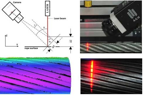
The vision system was configured as shown in Figure 1. The laser beam illuminates the rope at 90 deg in relation to its axis. The camera is set at a 45 deg angle with respect to the plane of the laser (Figure 1). With such a configuration, the following resolutions were obtained in each axis, respectively: ΔX = 0.15 [mm], ΔY = 0.15 [mm], ΔZ = 0.21 [mm].
The vision system acquires an image onto a monochrome CMOS [complementary metal-oxide semiconductor] sensor in such a way that the image shows only the laser line, which allows determination of a height profile. Following the assembly of height profiles as determined on successive images spaced from each other by ΔY = 0.15 [mm], a three-dimensional image of the rope surface is built (Figure 2). Using a system with three cameras arranged every 120 deg around the rope allows the construction of a complete image of the rope surface and inspection of the rope at speeds up to several thousand measurements per second.
A three-dimensional image of the rope surface is preprocessed prior to any measurement procedures. This is intended to remove any “noise” visible in the image of the rope surface and to prepare it for measurements (Figure 3a). The measurement algorithm is based on detection of the edges of strands, such as the small wires that form the surface of the rope and their segmentation (Figure 3b). Then, for each of the strands, a characteristic point is determined, which defines the largest height of the strand above the axis of the rope. The pitch length of a rope is measured based on the distance between the edges or characteristic points of a given strand. Parts of a strand are visible on the 3D image as white spots.
Another method to measure pitch length is to configure the vision system so the laser line is parallel to the axis of the rope. In that case, the rope surface shows an arrangement of strands forming the rope’s diameter. Pitch length in the proposed configuration may be measured for each of the strands. Analysis of the variation in pitch length allows indirect assessment of the wear of ropes or their damage (Figure 4). Attention should be paid to any strand fiber damage, visible in the image by distortion of the laser line. This additional information in a 3D image defines damage to the rope. Figure 4b shows a filtered height profile of the rope surface, prepared for measuring the pitch length of the rope.
Rope diameter is measured on the basis of an analysis of its cross-section acquired from a three-dimensional image of the rope. Coordinates of the rope center and the diameter of each of the cross-sections are determined. In the adopted vision system configuration, it is possible to determine the diameter every 0.15 [mm] along its axis. This allows detection of cracks on individual wires or strands on the surface of the rope and recording of such damage in the form of disturbances in diameter.
The use of three-dimensional images of rope surface allows detection of defects. The defects recorded during testing differ for steel ropes and fiber ropes. In the case of steel ropes, defects include bottlenecks or indentations in the arrangement of strands as visible in Figure 6a, and cracks to the strands, or wires forming the strand, shown in Figure 6b. In the case of fiber ropes, defects in the form of deformation of strand arrangement have been identified, as shown in Figure 6d, as well as frayed surface layer of strands as shown in the laser line image projected in Figure 6c. Those distortions also can be seen in the bottom part of Figure 6d in the form of local deformations of strand surface.
Summary: Better rope, cable quality
The method developed and described here uses a three-dimensional image of the rope surface to enable:
- Measurement of pitch length of any section of the rope
- Measurement of the diameter of any section of the rope
- Identification of damage and type of wear on the surface of the rope.
Recording and analysis of measurement results allows comparison of various parameters and their changes as a function of rope operating time in its application. Accuracy of this method and the frequency of measurements conducted as a continuous process far surpass the capabilities of current methods of measurement of the geometric features of steel ropes and defects on their surfaces.
– Andrzej Sioma, PhD, is with the AGH University of Science and Technology, Krakow, Poland. He is also a contributor to Control Engineering Poland; [email protected]. Edited by Mark T. Hoske, content manager, CFE Media, Control Engineering, [email protected].
Online
Control Engineering machine vision articles: www.controleng.com/machinevision
Control Engineering International articles: www.controleng.com/international