Electrical and instrumentation drawing software, rather than traditional CAD drafting methods, provides mining project engineers with major efficiency gains. Control Engineering Inside Machines, October 2010
Over time, skilled professionals develop effective methods for designing infrastructure and often are reluctant to deviate from those tried-and-true practices. Yet the more daring among them understand that experimentation often leads to breakthroughs. A case in point is LE80JV, the joint venture of LogiCamms and Electro80 that specializes in implementing large electrical and control system engineering projects. When the company was hired to work on a pair of large projects for the mining company Iluka Resources, it saw a chance to use electrical and instrumentation drawing software rather than traditional computer-aided design (CAD) drafting methods.
The projects involved mineral sands mining and processing in the Australian state of Victoria, with zircon being the end product. According to LogiCamms Vice President Garry McGrechan, “At the beginning, a decision had to be made whether to use traditional CAD drafting methods to produce the electrical and instrumentation drawings, or to use an intelligent design drawing package.” The decision was made to use Bentley Systems’ promis-e electrical design software to streamline the design phase and help meet the first project’s 18-month schedule.
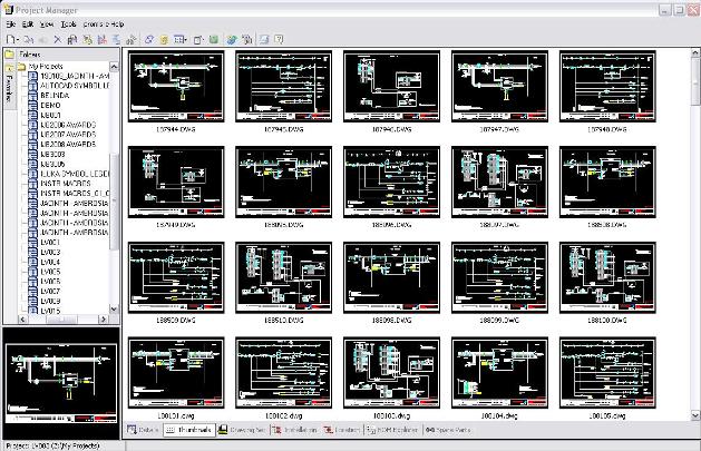
Using the software and a new design methodology, LE80JV completed Iluka’s Murray Basin mine project in 12 months instead of the 18 months scheduled. Also, as this project was coming online, Iluka’s Jacinth Ambrosia mining project in Western Australia was just beginning. By leveraging the design content and software used for the Murray Basin project, LE80JV generated a control-system design for this project in weeks rather than months. On both projects, LE80JV used promis-e to produce more than 2,000 drawings, including single line drawings, power and control schematics, interconnection diagrams, cable schedules, and instrumentation loop and power drawings.
The efficiencies gained were substantial. Here’s a look at the preparatory and real-time steps employed to design the infrastructure using new methods.
Generating schematics
Using the application programming interface (API) available in promis-e, the LE80JV team was able to automatically generate schematics, connection diagrams, and cable schedules for Murray Basin. The API allowed the team to change the design and check the results easily, and to leverage the control system design to automatically generate 100% of the drawings for the Jacinth Ambrosia project.
The software performed many functions automatically, including ID assignment, wire numbering, cross referencing, error checking, and report generation. The software’s “intelligence” speeds the design process by eliminating tedious manual “bookkeeping” work. It also prevents mistakes that occur through human error, such as duplicate IDs and wire numbers, missing or incorrect part numbers, etc.
As a preliminary step, LE80JV created an electrical and instrumentation symbol library for Iluka. Although an electrical symbol library is provided with the software, Iluka had many custom symbols that were needed to meet its design standards. Two additional advantages were the software’s flexibility to run either as an add-on to MicroStation or AutoCAD, and its ability to produce drawings in DWG format – the format Iluka prefers.
Another key preliminary step was training. Fifty percent of the design team (about 10 people) received promis-e training, including electrical engineers, instrumentation engineers, and draftspersons. Engineers from Iluka were also trained, which gave them confidence in the system as well as the design process.
Creating page templates
The software provides the option of automatically generating drawings from templates, which was a major part of the plan to maximize efficiency in the design phase. So, the next step was to create the page templates and drawing macros that make the automated generation of drawings possible. The page templates followed Iluka’s standards for page size and title blocks. The drawing macros consisted of schematic sections for various drive types, including direct-on-line (DOL) starters, variable speed drives, soft starters, and other common drawing elements. Each drive type included power schematics, control schematics, and interconnection diagrams.
It was then necessary to create the data files for the promis-e Project API Builder. Although the software allows drawings to be drafted manually, the API builder is an optional, custom programming interface that allows automated drawing generation by accessing commands and parameters stored in Microsoft Excel.
LE80JV’s typical Excel spreadsheet contains sections dedicated to power, control, and interconnection drawings. Each section includes commands for creating a page and placing the necessary macros. Additional parameters include data such as part numbers, power ratings, and circuit breaker size. This approach has the advantage of allowing design changes to be made by editing a single spreadsheet file, rather than numerous drawing files.
Software for design methodology
To generate the drawings, the user utilizes the API generator to follow the commands in the spreadsheet, combining the templates and macros as needed. The output is in DWG drawing files. LE80JV used a similar method to create the instrument drawings.
First, an instrument list was compiled for the project. Then templates and macros were created for all the instrument types (flow meters, density gauges, etc.). The data from the instrument list and templates was then combined with the API spreadsheet files via a custom program written by LE80JV. LE80JV then used promis-e, working through the API builder, to generate the instrument drawings.
The team also used the software for automatic report generation. The software automatically generated drawing reports, project revision summaries, cable schedules, and bills of material. It also includes a parts database containing detailed component information about all the devices used in the drawings, and this data was included in the reports.
Results with intelligent design software
Using intelligent design software rather than traditional CAD drafting methods, LE80JV made major efficiency gains. These included:
- Engineering and drafting hours reduced by 25%;
- A large number of drawings quickly regenerated in response to design changes;
- Drawing checking time reduced by 70%;
- Upfront engineering time reduced by 50% on the second project;
- Greatly reduced chance of human error on both projects, as a result of automated drawing generation; and
- Reduced time required for client input, because the client only had to check template files and API spreadsheet files.
Overall, “as an engineering tool, promis-e certainly fulfilled our expectations of simple mass production of electrical and instrument drawings,” McGrechan said. “It saved us valuable time on both projects, and its ability to produce files in DWG enabled us to meet our client’s format requirement.”
Bentley Systems
www.logicamms.com.au
– Also read from Control Engineering:
Electrical Design Software
3D Does It – Three-dimensional modeling and work cell simulation are providing real benefits today. Automotive OEMs and aerospace firms are pushing for more functionality, and demanding their suppliers join in the pursuit.
– Edited by Renee Bassett for Control Engineering, [email protected], www.controleng.com.