Skip to content
Search
Subscribe
Topics
Back
Topics
AI and Machine Learning
Control Systems
Digital Transformation
Edge and Cloud Computing
Industrial Cybersecurity
Industrial Networking
Mechatronics and Motion Control
Motors and Drives
Process Instrumentation and Sensors
System Integration
Webcasts
Research
Resources
Back
Resources
Magazine
Newsletters
eBooks
Podcasts
Videos
Case Studies
International Editions
Global System Integrator Report
Voices
Views
Automation Notebook
NEW PRODUCTS
Systems Integrators
Back
Systems Integrators
Browse System Integrators
All
The Global System Platform (GSP) supports engineering professionals.
2025 System Integrator Giants
A ranking of the top systems integrators
System Integrator Hall of Fame
View the latest and historical data
SI Corner
Systems Integrator Content
Global System Integrator Report
View the Digital Edition
System Integrator of the Year
Each year, a panel of Control Engineering and Plant Engineering editors and industry expert judges select the System Integrator of the Year Award winners in three categories (based on the size of the organization).
Events & Awards
Back
Events & Awards
Browse all Events & Awards
All
Product of the Year
The Control Engineering Product of the Year* program highlights some of the best new control, instrumentation, and automation products as chosen by Control Engineering‘s print and online subscribers. Qualified subscribers are asked to select products based on technological advancement, service to the industry, and market impact.
System Integrator Giants
The System Integrator Giants program (SI Giants) lists the top 100 system integrators among companies listed in the WTWH Media Global System Integrator Database, ranked solely on total system integration revenue.
Leaders Under 40
The Engineering Leaders Under 40 program* recognizes manufacturing professionals under the age of 40 who are making a significant contribution to their plant’s success, and to the control engineering and/or plant engineering professions.
System Integrator of the Year
Each year, a panel of Control Engineering and Plant Engineering editors and industry expert judges select the System Integrator of the Year Award winners in three categories (based on the size of the organization).
Leap Awards
The Leadership in Engineering Achievement Program (LEAP) Awards from Design World recognizes the most innovative products and components in the design engineering space.
2025 Leadership
Advertise
Articles
Workforce Development
How to continuously improve careers in automation, controls, instrumentation
Automation
Latest automation mergers, August 2025: software, robotics, sensors
The Downtime
The Downtime | Episode 25: Trendsetters
Vision and Discrete Sensors
A3: AI-based perception, vision-guided robots, visual language models
Vision and Discrete Sensors
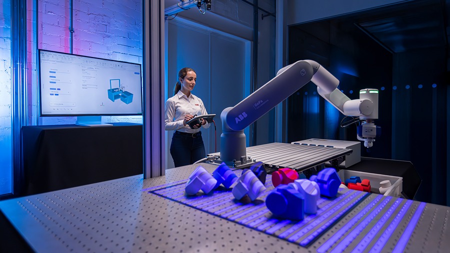
Machine vision model training, robot set-up, compact cameras
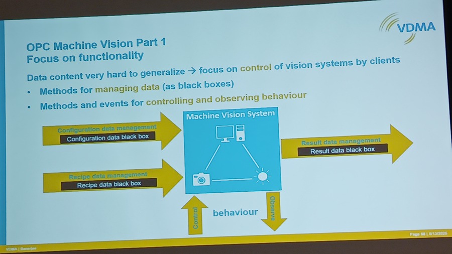
Vision and Discrete Sensors
Automate 2025: Machine vision standards update
Automation
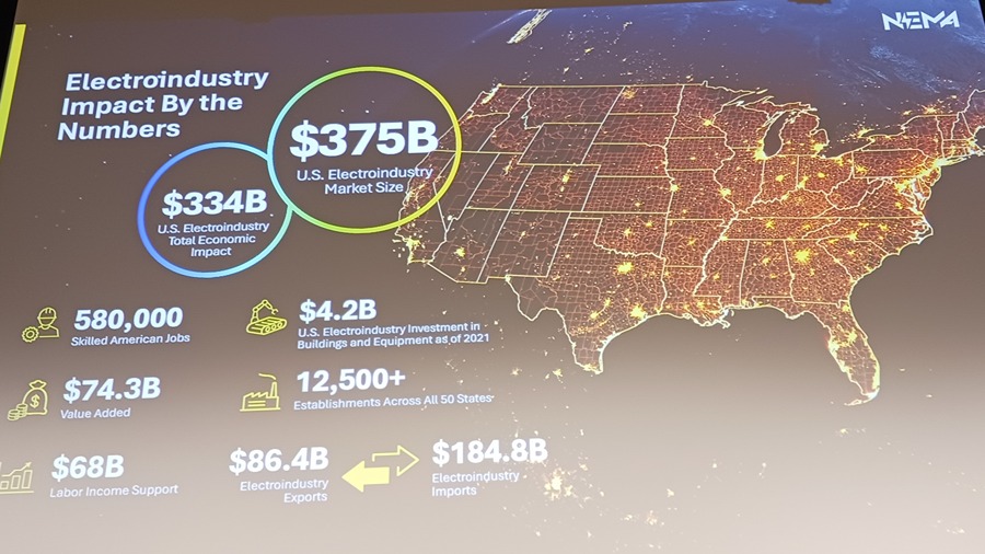
Powering the electric future: Technology, policy and the path ahead
Automation
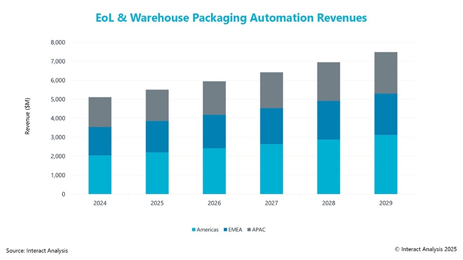
Report examines growth in packaging automation market
PID, APC
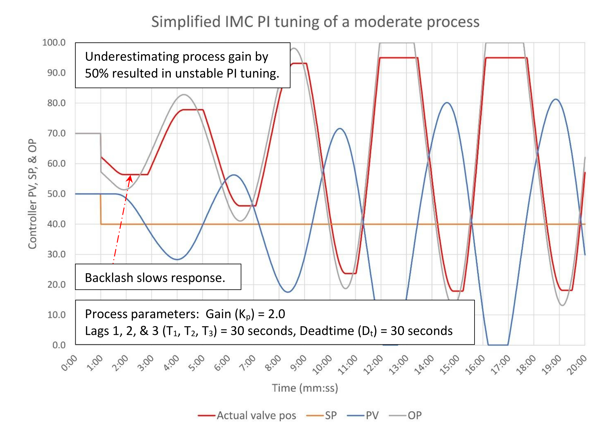
PID spotlight, part 20: How to tune with sticking control valves
The Downtime
The Downtime | Episode 24: Throwing It Back