Flow control by nature is quite forgiving, principally by being very fast and self-regulating. Self-regulation means the controlled variable reaches a steady state following any change in the position of the valve or the plant load with the controller in manual. And because its response is complete within a few seconds, flow is very easy to control manually, making it easy to control auto...
KEY WORDS
Process and advanced control
Control theory
Process analysis
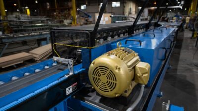
Process control valves
Sidebars: Linearizing an equal-percentage valve
Flow control by nature is quite forgiving, principally by being very fast and self-regulating. Self-regulation means the controlled variable reaches a steady state following any change in the position of the valve or the plant load with the controller in manual. And because its response is complete within a few seconds, flow is very easy to control manually, making it easy to control automatically. Though valve characteristics affect flow loop performance, it rarely needs special attention, except in critical processes like combustion.
Nearly half the control loops in a typical oil refinery or chemical plant are flow loops, many operating as the secondary (inner) loop in a cascade control scheme to control temperature or product composition. The slower, primary (outer) loops are insulated from the control valve and its behavior by the secondary flow loop. This article focuses only on the concerns of loops that directly move the valve.
Some loops cannot be cascaded to flow because the primary loop is nearly as fast as the secondary loop, or because accurate flow measurements are not available. For example, the resonant peaks of compressor pressure and flow loops are so similar in period that oscillations tend to be reinforced, requiring controller gains to be reduced to the point where cascading is less effective than single-loop control. In wastewater pH control, for example, reagent flow must be manipulated over a 100:1 or greater range-a difficult task for most flow measurement devices. For these types of control problems, valve characteristics become very important.
Steady-state valve characteristics
Any loop directly manipulating a valve is affected by the valve’s steady state, or inherent characteristics, which are defined as the relationship between the controller output and the resulting flow. Control valves are manufactured in two general characteristics: linear, and equal-percentage. Linear characteristics increase a valve’s opening in direct proportion to the signal applied to the actuator. Equal-percentage characteristics double the amount of opening at regular increments of stem position change. For example, an equal-percentage valve, with a rangeability of 50:1, will double its opening with each 17.7% increase in stroke. The gain of an equal percentage valve is directly proportional to the flow through the valve.
When the pressure-drop across a valve is constant, the inherent characteristic and installed characteristic are the same. However, in a majority of installations the pressure-drop across a valve decreases as flow increases because of losses inside an associated pump or compressor and fixed resistances of pipes and vessels in series with the valve. The reduction in pressure-drop with increasing flow causes the gain of the linear valve to fall, making its characteristic less linear as the pressure drop changes more and more. An equal-percentage valve, in the same situation, becomes more linear.
However, most valves are sized to operate over a pressure-drop range of 3:1, which gives these two valves installed characteristics equally spaced on both sides of linear. Only with unusually high pressure-drop ratios will an equal-percentage valve produce an installed characteristic more linear than a traditional linear valve.
When a reciprocating compressor is controlled using a recycle valve,the valve must be reverse acting (closing on an increasing input signal).
If that’s not enough, selecting a valve with linear installed characteristics does not always guarantee a linear control loop. For example, when 100 lb (45.36 kg) per hour of steam is mixed with 5,000 lb (2,267.96 kg) per hour of water, the water temperature will rise about 20 °F (10.56 °C). But if the water flow is doubled, the temperature rise produced by the same flow of steam will be only 10 °F (5 °C). Thus, the gain of temperature to steam flow varies inversely with water flow, and that gain can be compensated by using a steam valve whose gain varies directly with steam flow-an equal-percentage valve. Most temperature loops require equal-percentage characteristics, while most other loops are better using valves with linear characteristics.
Mischaracterizing the valve
Constant-volume delivery systems, such as constant speed reciprocating compressors, provide a linear response to flow because pressure is the integral of the difference between flow entering and exiting the system (see Reciprocating compressor diagram). Even when a reciprocating compressor is equipped with multi-step capacity reducing techniques, such as clearance pockets and/or suction-valve unloaders, a recycle valve is required to balance the load between stages.
In constant-volume delivery applications, the discharge pressure is controlled and the suction pressure is typically constant or may be at atmospheric pressure. Having constant pressure on both sides of the valve produces an identical installed and inherent characteristic; thus constant-volume system recycle valves should have linear characteristics. Unfortunately, this is often not the case and results in a system where the valve causes the loop gain to change as the load changes. (See diagram of ‘Reciprocating compressor fitted with equal percentage valve.’)
Following across the diagram, the pressure response to the first step change is lightly damped, perhaps too lightly damped. The second step change produces close to the optimum response. Each successive step change results in heavier damping as the valve closes and its gain is reduced. As a result, each successive pressure peak is greater and lasts longer. Installing a linear valve would produce pressure response similar to the second (optimum) throughout the range.
An equal percentage valve demonstrates changes in loop gain as the load changes.
Changing the characteristic
There are several ways to change the characteristic of an existing valve, but most come with compromises. Four of the most common means to change a valve’s characteristics are to:
Change the valve trim to obtain the proper characteristic. This is always the best solution, but sometimes the required trim characteristic is unavailable or the valve cannot be removed from service without a plant or process shutdown;
Change the cam in the valve positioner. This is also a logical solution, but cam selection may not provide enough curvature to convert a linear valve to an equal-percentage valve, or vice versa;
Apply a software-based characterizer to the controller’s output (see Sidebar); or
Use a smart valve positioner that provides programmable positioning of x-y coordinates on a graph to form any required shape.
But, and there seems to always be a but, the most expeditious solution may not produce the best possible results. For example, in a real application installing a smart-valve positioner on a multi-step compressor to make an equal-percentage valve perform like a linear valve required the valve to take four seconds to reach 65% of its travel and pass 25% flow. Installing linear trim in the same valve body produced the 25% flow with only 25% stoke in 1.5 seconds.
The control loop is capable of handling a small (20%) load disturbance, butvalve-stroking time (velocity limit) becomes dominant when a large load disturbance is encountered.
Velocity limit, expanding cycles
Most control valves, whether driven by an electric motor or pneumatic actuator, stroke at a fixed velocity rate. For example, a valve requiring 10 seconds for 100% stroke will typically stroke 10% in one second. This velocity limit behaves as a variable time constant in control loops. For small upsets, the dynamic response may be negligible, but when a large upset strikes a fast-acting loop, the stroking time may become the dominant factor.
This was witnessed of the recycle valve in a multi-step compressor installation. The original pneumatic positioner required 14 seconds stroking time in both directions. As it happened, the steps in compressor capacity affected by the unloaders and clearance pockets were unequal, varying between 14% and 34%. (See Control loop vs. stroke time comparison diagram.)
The diagram shows the expanding cycle is caused by the valves’ inability to follow the output of the controller at the speed with which it integrates. The velocity of the output wave varied directly with amplitude as well as frequency, and, beyond certain amplitude, the velocity of the output exceeded that which the valve could follow. This caused a continuously expanding cycle to develop until limits were reached-typically controller output limits. The ever-expanding cycle only appears during unusual conditions, and once begun, will not stop even if everything else returns to normal. Continuous limit cycling can be a very dangerous situation, only interrupted by manual intervention. Tightly tuned flow loops are especially sensitive to this condition.
Prevention of the expanding cycle can be achieved by slowing the integral time of the controller to that of the stroking time of the valve. The Control loop vs. stroke time comparison diagram illustrates a pressure controller with an integral time of five seconds operating a control valve with a 10 second stroking time. Doubling the integral time would stabilize the loop to the larger upset but would also double the integrated error in the response curve.
One possible solution would be to place a velocity limiter in the path of the integrator, set equal to the valve stroking time. This would prevent the controller from integrating faster than the valve moves. However, the best solution is to speed up the valve. In the multi-step compressor installation, a volume booster was installed between the positioner and the valve motor. This reduced the stroking time to two seconds, but when the pressure loop was closed, a limit cycle developed from the additional loop deadband introduced by the volume booster. This was confirmed when a simulation of the compressor behaved in exactly the same way after deadband was added to the simulated valve.
To obtain a faster stroking speed, without deadband, the pneumatic positioner was replaced by a smart valve positioner and later the valve trim was changed to linear characteristics.
Doubling the proportional band reduces the amplitude of the limit cycle andincreases its period, but the cycle remains. Doubling the proportional band alsodoubles the integrated error following an upset and is not recommended as a solution.
Deadband can cause limit cycling
Deadband is that dynamic element which causes a valve to stop whenever the direction of its control signal is reversed, and not reverse its motion until the control signal changes by a threshold amount. A deadband of 2% to 5% is common in valve actuators and is most often caused by friction in the seals and guides. The primary purpose of a positioner is to force the valve stem to follow the control signal by applying whatever pressure is necessary. Pneumatic positioners are typically proportional devices having a gain of 10 to 20, which can reduce deadband by that same factor. Smart positioners are faster, add integral and derivative action, and often include nonlinear gain and autotuning capability, making them more effective in eliminating deadband.
Level loops, due to their inherent non-self-regulating nature, will always limit cycle in the presence of deadband. Level loop limit cycles tend to be triangular, and their amplitude and period are functions of deadband and controller tuning, independent of the size of any upset. In a liquid-level loop, the limit-cycle amplitude actual increases with the proportional-band setting, so detuning is of no help. To remain stable, level loops require either a valve positioner, or should be cascaded with a flow loop.
Pressure loops frequently display limit cycle tendencies similar to liquid-level loops. Using the same pressure controller shown in the Control loop vs. stoke time diagram, a 3% deadband was introduced; the results show the ‘Deadband causes limit cycling’ diagram.
This diagram shows how the high gain and lag dominance of a self-regulating pressure loop combine to create a limit cycle in the presence of deadband. Doubling the proportional band reduces the limit cycle amplitude but increases the period. Doubling the proportional band also doubles the integrated error following a load change and is not recommended.
Not all control loops demonstrate a limit-cycle in the presence of deadband-flow loops typically do not. The effect of deadband in these types of loops prevents reproducible set-point response. For example, sometimes the measured value may overshoot the set point, and at other times undershoot the set point, depending on the direction of the last upset. The result is a stable process. These type control loops generally do not require a valve positioner and may control better without a valve positioner.
Remember this
So to help keep flow loops tuned, remember:
Slow loops should be cascaded to flow to eliminate the contribution of valve characteristics and dynamics;
Other than flow loops, any control loop that drives the valve directly should be established with characteristics that provide a constant loop gain-not simply a linear installed characteristic;
Performance improvements will offset the added expense of using smart valve positioners on all critical loops of this type; and
Don’t assume that low-amplitude stability alone is required-be sure fast loops are also stable following the largest upset they are likely to encounter.
See related ‘Product Focus’ in this issue.
Author Information
Francis Greg Shinskey is a recognized authority with more than 44 years of experience in applying practical solutions to solve complex process control problems for companies such as DuPont., Olin, and The Foxboro Co. Dr. Shinskey has authored numerous books and papers, and conducted seminars all over the world that have helped thousands of process control engineers tame misbehaving control loops.
Linearizing an equal-percentage valve
To linearize an equal-percentage valve usually requires building a complementary curve of 10-20 line segments. An alternative is to use a hyperbolic characterizer that uses a single parameter divider to obtain the desired characteristic, instead of adjusting multiple x-y coordinates.
The hyperbolic characterizer solves the equation: where y is its output and x its input over a 0-1 range, and L is the adjustable parameter. With L set at 1.0, the relationship is linear; set at 5, it simulates an equal-percentage characteristic with a 50:1 rangeability; set at 0.2, it converts a 50:1 equal percentage valve to linear. (Note if the valve is reverse-acting, these numbers are also reversed.) Intermediate settings can correct the installed characteristic for any pressure-drop ratio.