The international standardization of CAN Flexible-Data Rate (FD) is settled. The next step is the development of recommendations and specifications, or how to design CAN FD networks.
The CAN FD (CAN Flexible-Data Rate) data link layer submitted to the international organization for standardization (ISO) has passed the Draft International Standard (DIS) balloting without negative votes. This means, after implementing the observed comments, the ISO 11898-1 standard will be published. More than 100 comments, mainly of editorial nature, are already observed and implemented. Now, it is just a matter of time, for the ISO 11898-1 document to be published as the International Standard.
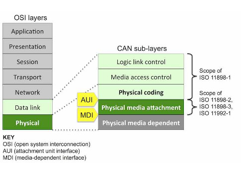
This standard also specifies a part of the physical layer, the physical coding sub-layer, according to the open system interconnection (OSI) reference model. The CAN FD physical media attachment (PMA) sub-layer describing the transceiver characteristics is internationally standardized in ISO 11898-2. This document has been submitted for DIS balloting. It also comprises the optional low-power mode (formerly in ISO 11898-5) and the optional selective wake-up functionality (formerly in ISO 11898-6). System-related specifications have been deleted. The new ISO 11898-2 standard specifies just the transceiver characteristics. The physical media dependent sub-layer is not in the scope of ISO 11898 series. It is highly application-specific and might be specified by other ISO standards or other associations (such as CiA, IEC, or SAE).
ISO also standardizes the conformance test plans for ISO 11898-1 and ISO 11898-2 implementations. The related standards, ISO 16845-1 and ISO 16845-2 are under development. ISO 16845-1 has been submitted for DIS balloting, and ISO 16845-2 is in committee draft (CD) voting. The test houses C & S Group and IHR are already developing conformance test prototypes. Most of the automotive chipmakers are in the process to integrate CAN FD cores into their micro-controllers. Many of them have licensed the IP module from Bosch. There are also several vendors providing a self-implemented CAN FD ASIC/FPGA. Engineering samples of CAN high-speed transceivers qualified for 2 Mbit/s and 5 Mbit/s are already available from several companies.
Next step: Using the longer data frames
The standardization of the CAN FD data link layer and physical layer is settled. Even the first higher layer protocols (transport layer and application layer) make use of the longer CAN FD data frames. This includes the so-called ISO transport layer as standardized in ISO 17765-2. The first implementations by Vector and Volkswagen were tested last October during a CAN FD plugfest organized by CAN in Automation (CiA). Also the XCP calibration protocol version 1.2 specified by the nonprofit ASAM association makes use of the 64-byte data fields. The automotive open system architecture (Autosar) version 4.2.1 also supports CAN FD.
The CiA CANopen special interest group (SIG) application layer currently develops the CiA 301 version 5.0, which will be based on the CAN FD data link layer. Most of the CANopen protocols will remain as they are for more than 20 years. However, the public domain operating system (PDOS) will be prolonged to 64 bytes. The number of mapping entries will be still 64. This means it is not possible to map more than 8 byte bit-wise. Byte-wise mapping is preferred. The bigger change regards the SDO protocol. It will be completely changed: The Universal SDO protocol will be structured better and will be easier to implement. It is still under development.
The SAE is discussing, in its J1939 CAN FD task force, how to make use of the longer frames. In parallel, the CiA IG (interest group) commercial vehicles prepare the CiA 602-2 application layer proposing a mapping of J1939-71 parameter groups into CAN FD data frames. It provides an optional safety/security field. The CAN identifier contains the source address as specified in SAE J1939-21. It is intended to reuse the 8-byte parameter groups as specified in J1939-71. In the future, longer or shorter parameter groups could be specified and mapped into frames as specified in CiA 602-2.
Learn more about designing a physical CAN FD network and configuring bit-timing
The challenge: Designing a physical CAN FD network
Specifying higher layer protocols using the longer CAN FD frames is simple compared to the design of physical networks with transmission speeds higher than 1 Mbit/s. Do not underestimate the challenges in designing multidrop networks running at higher bit-rates. Already 1 Mbit/s is a challenge. The automotive industry has not used Classical CAN networks with the maximum bit-rate in cars and trucks. Some truck makers use 667 Mbit/s, or even 800 kbit/s.
If two nodes communicate and all physical layer elements (input/output (I/O) ports, connectors, cable, etc.) provide an impedance matching to the termination at both ends, there are no disturbances on the bus-lines. Of course, the network will need connectors and cables. The limitation is just the speed of light, or more precisely, the maximum speed of electrical pulses in the cable. Theoretically, you can reach 10 Mbit/s at about 100 m.
If there are more nodes communicating, things become more complex. In theory, bus-line topologies terminated at both ends with very short unterminated stubs are the optimum. Star and hybrid topologies are more challenging, increasingly with higher bit-rates. From first experiences, star topologies with just a few branches are possibly running with 2 Mbit/s. In this case, the star center should be terminated with two 30-Ω resistors.
Topology is just one topic when designing a physical CAN FD network. It all starts with the tolerance of the CAN controller’s oscillator. The ISO 11898-1 standard provides five requirements, which you have to meet when calculating the allowed tolerance of the oscillator. To make it simple: Up to transmission speeds of 4 Mbit/s, the same tolerance as in Classical CAN guarantees a robust communication. For higher speeds, more precise and more expensive oscillators are needed. In any case, it is specified in ISO 11898-1 that the frequency of the oscillator shall be 80 MHz, 40 MHz, or 20 MHz. When the oscillator is implemented by means of configurable cascaded phase locked loop (PLL) circuitries, the user should take care to configure them in a way that the tolerance requirements are met.
Configuring the bit-timing
Configuring the bit-timing is the next topic. Of course, the configuration of the arbitration bit-time is the very same as in Classical CAN. You have to set the bit-rate prescaler, the propagation segment (always one time quantum), the propagation and phase segment 1 (often just one setting), the propagation segment 2, and the synchronization jump-width. In order to minimize the quantization error, when switching to the higher bit-rate, the number of time quanta per bit should be large enough. Bosch’s M-CAN module allows 385 time quanta per bit.
The detailed parameter setting for dedicated bit-rates is not in the scope of ISO 11898-1. CANopen FD (CiA 301 version 5.0) and CiA 602-1 (CAN FD physical layer for commercial vehicles) will provide such specifications for different bit-rates. Also, SAE 2284-4 will specify the CAN FD bit-timing for passenger cars as well as some other details of the CAN FD physical layer design. The document is still under development.
The data-phase bit-timing, which is independent of the arbitration bit-timing, uses the same parameters as mentioned above plus the transmitter delay compensations (TDC) and the TDC offset. The CiA 601-1 CAN FD physical layer design specification recommends the enabling of the TDC function.
The CiA 601-1 document provides some physical layer design rules for CAN FD nodes. The access is limited to CiA members. However, interested parties willing to review and comment on the specification may request a personalized copy from the CiA office. The confirmation of sample points for both bit-rates should be the very same in all nodes. This increases the robustness of the communication. It is also recommended to configure the bit-timings with a resolution, meaning the maximum possible number of time-quanta, in order to reduce the quantization error. This leads to an increased phase margin. CiA also recommends using transceiver chips qualified for higher bit-rates. They feature less asymmetry, which remains more phase margin for the ringing caused by the chosen topology and other physical layer effects.
The transceivers feature different loop delays for the recessive-to-dominant and the dominant-to-recessive transitions. The symmetry of these two loop delays depends on the symmetry of the internal transceiver delays and on the resistive and capacitive busload. The asymmetry of the transceiver loop delay shortens or expands the bit in the arbitration phase and the data phase. Towards higher bit-rates, the symmetry becomes more and more important. The ISO 11898-2 specifies minimum/maximum symmetry values for 2 Mbit/s (-65 ns/+40 ns) and for 5 Mbit/s (-45 ns/+15 ns).
The symmetry of the RxD signal on the receiving node is defined by the symmetry performance of the transmitting and receiving node. To guarantee a robust communication between two or more nodes in a network, the transceiver Tx delay symmetry of the transmitting node and the transceiver Rx delay symmetry of the receiving node must be very accurate. The loop delay symmetry cannot cover this in total. It is possible that one device in the network has a transceiver with a very symmetric transmitter part and an asymmetric receiver part. The behavior of a transceiver from another supplier may behave vice versa. Therefore, in the CiA 601-1 specification, additional parameters were defined for the transmitter and receiver symmetry (e.g. tREC(RxD)min = 110 ns and tREC(RxD)max = 225 ns for 5 Mbit/s). The document also describes how to calculate the jitter-bit length seen by the receiving node. These values consider only the influence of the transceiver. Additional effects such as clock tolerance and the phase shift of the network are discussed in /CiA601-3/, which is still under development.
The phase margin depends also on the oscillator frequency and some nonbit-rate reasons. This includes the bit asymmetry caused by the transceiver and other physical layer elements and the unstable RxD signal caused by the ringing. The ringing on the bus lines comes from the used bus topology.
Network designers should also consider temperature-depend effects. For example, the isolation material of cables can change the impedance depending on the temperature. In the CiA 602-1 CAN FD physical layer specification for commercial vehicles, it is not recommended to use PVC cables. Asymmetric, printed circuit board (PCB) layouts or connectors can also cause ringing. Therefore, the CiA 602-1 specification for CAN FD physical interface for commercial vehicles proposes that the untwisted length of the wire in the area should be as short as possible (in maximum 50 mm).
There are more recommendations given regarding electrical connector parameters. Even the pinning of angular connectors is an issue at higher bit-rates. The CAN_H and CAN_L pins should have the same length.
In order to suppress ringing in star and hybrid topologies, special circuitries could be used. Denso’s has submitted its ringing suppression technology to CiA for standardization and submission to ISO. It is described in CiA 601-4, which is under development. The basic idea is to change the impedance of some nodes dynamically. It is switched on for a short part of the bit-time and then switched-off again. In CiA 601-4, the maximum start time is specified with 50 ns and the end-time between 200 ns and 410 ns.
General Motors prefers another solution: a bus-line topology with all nodes terminated locally. In March 2015, the intended GM wiring harness was tested successfully during the CAN FD plugfest in Detroit organized by CiA. GM likes to use 24-m, bus-line networks with 20 nodes and not terminated stub-lines. The maximum stub-line is 1.7 m.
More experiences are necessary
CiA will organize the next CAN FD plugfest, when new products are launched or additional network approaches are submitted for testing. Additionally, CiA will collect experiences and organize the exchange of knowledge within the IG CAN FD and the IG commercial vehicles. Additional participants are welcome. The upcoming CAN FD Tech Days will update newcomers with Classical CAN background in CAN FD technology. Several papers related to CAN FD topics will be presented at the 15th international CAN Conference in Vienna on Oct. 27 and 28.
– Holger Zeltwanger is managing director, CAN in Automation, a CFE Media content partner. Edited by Joy Chang, digital project manager, CFE Media, [email protected].
ONLINE extra
– See additional stories from the author linked below.