Following these best practices can help prevent voltage drops, overload trips, and other common VFD faults and serious failures before they occur.
Variable frequency drive (VFD) technologies support an expansive range of machine tasks and robotics in automated warehouses, logistics, manufacturing, and process industries. Properly sized and configured VFD systems can help optimize performance, save energy, and permanently lower machine and robotic lifecycle costs. Conversely, faults and failures can escalate into costly downtime. Operators must quickly identify and resolve problems. Identifying a fix may be simple or reveal a complex problem, which is why fault and failure prevention is always the best strategy.
Properly derate VFDs
Preventing faults and failures starts by right-sizing the VFD for the machine task. Single-phase input voltage on a VFD with 3-phase input is common in many automation applications. Depending on the horsepower and voltage rating, drives can accept single-phase input voltage without derating the output current. If ratings are exceeded, a larger 3-phase drive is required when using single-phase input voltage. Most 3-phase drives up to 30 hp at 240 V, 60 hp at 480 V, and 60 hp at 590 V input can have single-phase power applied. However, it is important to be aware that single-phase power will cause higher dc bus voltage ripple.
For proper drive sizing, the output current should be derated by 50%. When derating, double the current but not the horsepower rating. For example, a 10 hp, 240 V drive is typically rated at 29 A continuous current, but the derated output current will be half, or 14.5 A, because of the single-phase input to the drive. The input current rating for the drive remains the same. Drive software doesn’t recognize input power as single-phase. Therefore, the motor overload parameter must be scaled to limit output current. The motor overload parameter for the drive should be set according to the drive’s true output rating, not the derated value. In the aforementioned scenario, assuming the motor’s full load amp (FLA) rating is 12 A, the VFD’s overload parameter should be set to 12 A divided by 29 A, or 42%, plus additional derating that may be required for the application.
VFDs have an adjustable overload parameter to protect the motor. Drives come standard with electronic thermal overload protection allowing the VFD to deliver 150% of the rated output current for 1 minute and higher current levels for shorter periods. The overload can be adjusted to protect smaller motors. When using a larger VFD on a smaller motor, the output current must never exceed the motor’s FLA rating under normal operation. This requires scaling down drive output current capacity by identifying the motor’s FLA rating and dividing that value by the drive’s output current rating to get the correct percentage for the motor overload parameter. The minimum setting for most VFDs is 25% to 30%. If the motor rating is lower, the drive won’t fully protect the motor.
Wiring and filter protection
Additional precautions apply to wiring, isolation, grounding, and shielding. A VFD generates a pulse-width modulated output waveform containing high frequency components including radio frequency interference (RFI) and electromagnetic interference (EMI). Cable lengths exceeding 33 ft can pick up noise, stray capacitive effects, and have resistive voltage drops. It is important to not exceed the maximum recommended cable length between a VFD and a remote analog input speed reference signal. As wiring distance increases, the exposure to higher noise levels, resistive voltage drops, or parasitic capacitance increases. Consult the drive manual to ensure proper wire gauge ratings. A separate 10 V dc power supply may be needed if the voltage drop across the long cable length is significant. This also holds true for a 4-20 mA signal, in which case a shielded cable with a minimum of 300-V jacket insulation should be used.
VFD power output connections carry high levels of high frequency voltage contributing to EMI. Screening (or mesh) of the output power cable is needed at both the VFD and motor ends. A copper braid screen with full 360-deg clamp coverage works to minimize emissions. The motor cable screen must be terminated to the drive heat sink or mounting plate and to the motor frame.
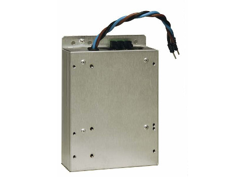
Typically, a line filter to the drive input is unnecessary, except in certain cases, such as to meet CE compliance or when noise from the drive reflects back onto the input power and causes interference. If the motor cable length exceeds 100 ft, an RFI filter should be connected on the VFD input to attenuate high frequency noise (see Figure 1).
Common fault parameters
Knowledge about common fault parameters is key to prevention. Whether a stock VFD in conveyors, fans, and cooling towers, or a specialized unit designed for presses, extruders, roll-forming machines, lathes, and routers, a VFD will generate a low-voltage fault when the voltage drops below set parameters. A VFD may report a low-volts fault when the drive dc link voltage drops below 62% of the nominal level for the high setting (480 V ac) and 50% of nominal for the low setting (400 V ac). This can be stated as:
480 V ac x 0.62 x √2 = 421 V dc
The nominal dc link voltage is:
480 V ac x √2 = 679 V dc
The +10% and -15% voltage tolerance in most manuals is the recommended operating range to allow the drive to maintain premium efficiency and proper motor current. Drives can run below these tolerances, but reduced voltages can have unpredictable effects on motor current, temperature, energy use, and overall performance.
Some automated processes rely on generators to maintain seamless operation. Switching from line power to a backup generator is a common practice. Most portable backup generators have a larger than ideal voltage swing on their phase-to-phase voltage outputs, compared with drives, which generally should have less than 2% imbalance on their input voltage terminals. Larger variances can induce greater ripple on the dc bus capacitors, which can damage the capacitors and other power components.
Protective devices are designed to prevent VFD exposure to unbalanced input power and to allow for power-up only when voltage is within tolerances and proper delay times are met. VFDs come equipped with surge guards in the input rectifier circuit. Additional safeguards against voltage swings, such as surge arrestors and other external protection, can prevent severe input disturbances. During a switch from line power to a standby generator, most drives need a minimum of 2 minutes before reapplying power. Ignoring this guideline can blow the input fuses, trip the breaker, or even damage the charge relay circuit.
A 3% line reactor can improve the situation when input power exhibits moderate voltage spikes. Another option is to add a voltage monitor with a time delay, which can provide protection trip levels to shut down the drive in the event of under-voltage, over-voltage, loss of phase, and voltage imbalance between phases.
Deploying an isolation transformer
A drive isolation transformer can isolate grounding and noise-related input power problems that can potentially affect drive performance and operation. A drive isolation transformer between the VFD and the power source offers several benefits by ensuring that no direct electrical connection exists between source and load. The placement of grounded electrostatic shielding between and around primary and secondary windings makes a drive isolation transformer unique. The shielding provides up to a million-fold decrease in the capacitive coupling involved in transferring common-mode voltage disturbances.
Common-mode transients are those appearing between ground and neutral of the ac system circuits. Although those parts are typically bonded together, they cannot be presumed to be bonded throughout an entire power system. Common-mode transient disturbances arise from switching-mode power supplies, drive operation, arc welders, lightning, or even normal operation of equipment, such as those using stepper motors. Some isolation transformers can also block normal-mode transients appearing between line and neutral.
Although they are more expensive than monitoring devices, an isolation transformer provides better protection than a line reactor and is appropriate at times, such as installations in close proximity to a substation. In utility company operations, for example, daily power-up of a substation capacitor bank in an industrial park may cause transient voltage spikes, which can be amplified by reflection from nearby capacitors. If a facility in the park has several small drives rated at 7.5 hp, normal-mode transients can cause these drives to shut off, resulting in process downtime. An isolation transformer can help prevent disruption.
Practical installation tips
A VFD can sit unused and without power for a short time without service. If a VFD has been stored for longer durations, the dc bus capacitors must be reconditioned. The electrolyte inside the bus capacitors changes state when unused for long periods. Reconditioning requires running the drive with no motor leads connected for at least 8 hours before trying to run the drive under load. Repowering the drive under no load brings the electrolytic charge back to a proper charged state.
Line reactors improve the true input power factor and reduce crosstalk between drives. If the supply transformer kVA rating is greater than 10 times the VFD kVA rating, a line reactor is recommended to reduce power-line transient voltages caused by capacitor switching, line notching, dc bus overvoltage tripping, inverter overcurrent, and overvoltage conditions as well as to minimize VFD damage in case the transformer shorts out. Line impedance depends on the short-circuit rating of the drive and on the supply power distribution transformer. Specifically, the line impedance must be greater than or equal to the ratio of the supply source transformer’s rating to the VFD short-circuit rating.
Use separate conduit for input power, output power, and control wiring. Follow these guidelines when connecting the VFD power and control wiring:
- Install input ac power wiring in its own rigid steel conduit.
- Install output motor wiring in its own rigid steel conduit.
- Install control wiring in its own rigid steel conduit.
- Low-voltage dc control wiring and 120 V ac control wiring should be in separate conduits.
- Both twisted pair and shielded wire are sufficient when wiring to the VFD control board. In addition, 2- and 3-wire connections are recommended. For many drives, the minimum wire size is 18 AWG.
Ground connections must be tight and properly grounded. Connect the shield to ground at only one end of the cable to avoid ground loops. The shield at the VFD should be connected to the chassis ground lug. Always remove power from the VFD prior to connecting the shield to the ground lug.
Control and feedback wiring should be separate from power wiring by at least 12-in. A caveat would be in installations with multiple VFDs—input power wiring can be in the same conduit, and the control wiring can be in the same conduit, but the output wiring for each motor must be in separate conduits. If one VFD is used to operate multiple motors, the output wiring for all of the motors can be in the same conduit.
Use the drive on a grounded system. Never use a floating ground. Some manufacturers do not recommend operating with a floating input on any sub-micro or newer designed drives. If there are no disturbances on the line, the drive should run fine, but serious common-mode noise could cause nuisance tripping or worse. Certain legacy VFDs use a string of resistors between the dc bus and ground, which mitigates common-mode noise. Some integral-horsepower drives also use a resistor string, so using the floating ground on these is probably acceptable. However, a floating-point system is not recommended for newer drive technology.
Avoid using time-delay input fuses. They are not made for protecting VFDs and other solid-state rectifier front-end equipment. Time-delayed breakers allow the metal oxide varistor (MOV) to continue drawing current, which can cause the drive to burn up or the MOV itself to blow before the breaker ever trips. Use either branch circuit protection via a circuit breaker or a disconnect switch and fuses to comply with NFPA 70: National Electrical Code (NEC) and local codes.
Select a circuit breaker or fuse rated at 1.5 times the input current rating for constant torque drives and 1.25 times the input current rating for variable torque drives. Regardless of the input current rating, the minimum rating should be 10 A to accommodate inrush during power up. Use fast-acting, current-limiting type fuses with low I2t values and 200,000 AIC rating or equivalent.
A contactor or disconnect switch between the VFD and ac motor is not recommended. Such devices should only be operated when the VFD is in a stop mode. Otherwise, they can cause nuisance tripping. Possible noise from the output feeding back into the control board through the low voltage power supply can result in damage to the control or driver board.
If a contactor is required, an early-break auxiliary set of contacts on the device should be interlocked with the VFD external fault input or stop input. If the device is opened while the VFD is running, it will stop the drive and immediately cut off VFD output power. Use a minimum time-delay of 100 msec. If wired to the VFD stop input, the stop method must be set to coast. Always allow the drive to completely stop the motor before restarting.
Do not cycle the input power more than once every 2 minutes. Drive manuals specifically warn that switching a drive off and on without waiting 2 to 3 minutes is detrimental. Applying input power more quickly causes the inrush limiters to overheat in the input precharge circuit and eventually burns them out. The dc bus capacitors don’t have enough time to discharge. If the input circuit doesn’t have time to stabilize, additional input current can blow the input fuses or circuit breaker and damage the charge relay circuit.
The precharge circuit allows a certain time limit for the inrush limiter to send current through to charge the dc bus capacitors. The inrush limiter resistance changes with temperature. The hotter the limiter gets, the lower the resistance value. When that precharge time ends, the relay cuts off and the capacitors hold the charge. When the drive is powered down, this voltage bleeds off through resistors in the discharge circuit. Power reapplied too quickly passing through an inrush limiter that hasn’t had time to cool down to an acceptable resistance level can blow fuses or possibly damage the precharge circuit. One solution is to install an external time-delay relay or voltage monitor circuit at the drive input. If voltage drops below a set level, the monitor cuts off and allows zero power back into the drive until 2 to 3 minutes have passed to ensure voltage has stabilized to an acceptable level.
Do not use a ground-fault circuit interrupter (GFCI) if the drive is equipped with a filter. A GFCI can cause nuisance tripping due to parasitic capacitance producing leakage currents between the motor power cable lines during VFD operation, connecting multiple drives to the same input source, and using RFI filters on the input side.
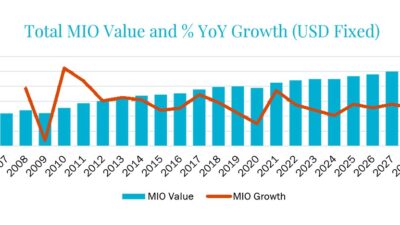
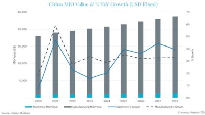
Regardless of whether it’s used in machining, material handling, or pump and fan applications, a VFD is an essential tool at an affordable price for improved automation control, reliability, energy efficiency, and motor protection when specified and installed properly (see Figures 2, 3, and 4). Motor drive requirements for automation should be analyzed on a case-by-case basis. These strategies and a qualified supplier can help users prevent voltage drops, overload trips, and other common VFD faults and serious failures before they occur.
Thomas Robbins is the call center supervisor for the Sales Support Team at Lenze Americas. He started at the company in 2005 and has more than 20 years of experience in technical support and field service. Robbins previously worked with Fanuc America Corporation and has a BS in engineering technology from Northeastern University in Boston, Mass.
This article appears in the Applied Automation supplement for Control Engineering
and Plant Engineering.
– See other articles from the supplement below.