Controls engineers are often brought in for the first time during the final steps of machine building to help tune everything. To achieve the desired performance, the machine must be designed so that mechanical resonances do not exist, or exist far above the desired control bandwidth. Earlier collaboration is better.
We’ve all been there: 1:00 a.m. sweating in a bunny suit, locked in a cold, dry clean room with the same goal: get a production machine up and running. It’s a dance known too well, comprising vibrations, under-damped control oscillations, and poor mechanics. When these mission critical controls-related issues show up after the machine is built, it’s fair to be frustrated. This happens all too often.
Identifying and solving problems late in the design cycle with a “guess-and-check” approach costs significantly more than catching problems earlier during the design phase, although it is accepted as the standard machine design process. Guess-and-check machine design is not only expensive, it’s also frustrating and unnecessary. Advances in system simulation and the introduction of cost-effective, off-the-shelf simulation tools can circumvent these costly mistakes in machine building.
Controls engineers are often brought in for the first time during the final steps of machine building to help “tune” everything. This behavior, and the fact that it happens so late in the design cycle, almost entirely explains guess-and-check machine building. Arguably, tuning is one of the most important steps in building a machine, as it determines how much of the machine performance is realized. However, to achieve the desired performance, the machine must be designed so that mechanical resonances do not exist, or exist far above the desired control bandwidth. If resonances exist in the final machine, controls engineers must “tune them out” through a process of changing tuning gains and implementing digital filters.
While filters can stabilize the system, significant resonances still limit the bandwidth of the system, even with the filters in place. With each resonance and associated filter comes a cost of performance, and the sum cost of all the resonance/filter combinations is often noticeable in the final machine performance. If the controls engineer was consulted earlier in the design process, ideally before a single piece of the machine was built, many performance-reducing resonances could be eliminated, improving machine performance.
Habits, cost, standards
Unfortunately control problems are difficult for most to conceptualize. Even the simplest system, like a motor with a flywheel directly connected to the shaft, will have a resonance (often large, but high frequency). High-frequency resonances are easy to solve and often don’t impede performance significantly. Insert a belt and the system will have lower resonances that can vary, machine to machine.
Design decisions like these are made for a variety of reasons—habit, cost, and industry standards—but often are not made with controls in mind. Simulation tools can help machine designers identify controls problems early in the design process to prevent costly redesigns and help mitigate the risk of finding a severe controls issue in machine testing and commissioning.
Simulation tools that integrate into production environments have been around for a long time. However, they remained neglected by the majority of machine designers in lieu of the usual guess-and-check process. Recently, hardware in the loop (HIL) has started gaining ground, which blurs the line between simulation and testing. As affordable and powerful simulation options are introduced, there are fewer and fewer reasons to keep simulation out of the machine design process.
HIL is a term to describe a development and testing strategy. It is often used in embedded system development to design and test individual components that may not be available during the design stage of the project. Most projects are broken up so that multiple teams, such as mechanics, controls, and software, may work independently. By using HIL, each team can work on their individual components, while using a simulation environment to simulate what the other teams are working on. This makes it possible to achieve a more streamlined development process and cross validation, ensuring each component functions as it should, while adding design feedback loops when a team finds a problem. By catching issues at the design stage, the cost of redesign is a fraction of what it would be if it were found after the machine was built. It also makes it possible for designers to experiment without worry of damaging an expensive machine.
Hardware in the loop support
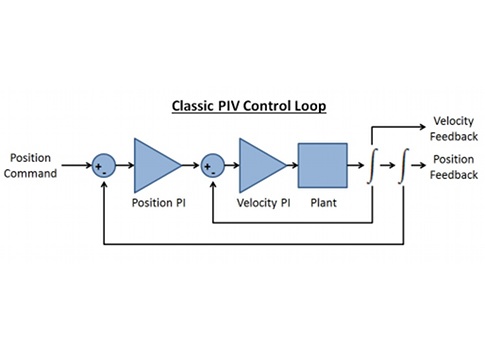
Various companies support HIL. The same control system components that will be deployed in the machine can be used in an HIL system early in the design process to gain insight into system behavior. As an example, a servo drive can generate the motion trajectory and close the servo control loops while an advanced industrial controller can simulate the plant (in this case, everything past the servo drive, including motors and mechanics).
The servo drive will generate motion trajectories, execute control loops, and provide a current command to the plant simulation running on the controller. The current command is transmitted from the servo drive’s analog output to an analog input module in the controller chassis. The controller executes the plant simulation in real time (mechanics, friction models, feedback device, delays, and noise are included here). From the plant simulation, a feedback signal is generated on the control system, which is connected to the servo drive’s feedback connector, completing the control loop.
System design software is used to design a model to take a torque input (via the analog input) and construct a plant model. This may be a single or double integral system, depending on the desired simulation. In the case of the servo drive, a double integral system will be simulated, and its position sent back to the drive.
More advanced users may implement complex friction models or other non-linear behavior to learn about their controls performance in great detail. New users will be surprised at how easy it is to construct a simple model. Even if the controls model is so simplistic as to make it trivial with regard to controls performance, there is a great deal of benefit to the software side of system design.
Configure, test, use
A setup like this makes it possible for a designer to use production hardware and write production software to communicate to the production hardware even though the physical mechanics do not yet exist. Running simulations with production hardware is the best way to ensure the system will meet expectations. HIL also makes it possible to use existing hardware diagnostic tools. In this case, software can be used to configure, test, and tune the servo drive. The ability to use existing diagnostic software can leverage powerful tools to analyze the simulation.
If users apply software to take a frequency response measurement of the system, it’s possible to quickly identify a resonance in the mechanics and then tune the drive. Follow-up measurements to quantify the performance of the motor should be made to verify no other non-linearities like friction are affecting the system. Applying the powerful tuning tools in software, the user can fine-tune and test tuning solutions before the machine is built.
In the design process, time must be spent to quantify the performance required for the machine and the application. First, keep in mind historical performance of previous machines. Don’t design for arbitrarily improved performance; design for what is needed. Second, define the real performance parameters that affect the user, such as servo bandwidth and settling time to avoid chasing “better performance” with no goal in mind. Once the initial tuning is determined, the user can proceed to simulate motion and look at the data on a virtual scope. Resonances that are left unaddressed in the design stage will start to show up. However, when using HIL practices, users can review these in simulation before the machine prototype is even built—a nice alternative to sweating it out in a clean room at 1:00 a.m. with a looming deadline.
Simulation results
The simulation results should provide users with a good idea of how the machine will perform, and this should also indicate if the machine will meet the performance requirements. If the system still does not meet performance goals, the simulation environment allows changes to be made easily.
For example, is more power required or a stiffer set of mechanics? Try changing these factors in the simulation environment and understand what is important to the system dynamics. The speed and ease of changing the system in simulation makes it possible for the different design groups to work together to understand the problem and fix it more quickly than if actual changes were required for the test. The speed and economy of changes in simulation is very attractive to anyone who has worked on a real machine that didn’t meet specification.
So how does HIL change guess-and-check machine building? It’s simple: Using the same advanced tools to analyze these simulations as on the real system will uncover controls problems before the machine is built—providing significant cost and time savings.
– Paul Streder is senior software engineer – industrial automation, Kollmorgen, and Nate Holmes is product manager – motion control, National Instruments. Edited by Mark T. Hoske, content manager, CFE Media, Control Engineering and Plant Engineering, [email protected].