When ISA's S88 committee released ANSI/ISA S88.01 Batch Control: Models and Terminologythe process control industry received a method that allowed project planning and estimating to move from an art to a science. The standard creates basic modules that never loose their independent identity, functionality, and interconnectivity.
KEY WORDS
Process control & instrumentation
Batch control
Control architectures
Object technology
Specifications
System analysis or design
System integrators
Sidebars: S88 definitions
When ISA’s S88 committee released ANSI/ISA S88.01 Batch Control: Models and Terminology the process control industry received a method that allowed project planning and estimating to move from an art to a science. The standard creates basic modules that never loose their independent identity, functionality, and interconnectivity.
Using S88 and recommendations that follow can help ensure users create useful and accurate project specifications.
Historically, process facilities were designed to produce a defined throughput of a specific product. Material balance equations and equipment selections were made to meet throughput requirements, plus maybe another 10%. Unit managers could be heard bragging when a facility was producing 25% more than design. Seldom were calculations and designs developed for lesser throughputs. When market demands diminished and production rates were reduced, the oversized equipment, different process dynamics, and control system tuning parameters made it difficult to produce a quality product. Similarly, when competition, regulation, or market demands required changing the product, facilities often required extended shut downs and sizable investments to prepare the facility for the new product.
Today, requirements for flexibility and time-to-market have become key business drivers. To quickly produce a new product, in customer-required quantities, producers are turning to batch processing and process automation. Agile is the buzzword-modular is the way to achieve it.
Achieving a flexible batch facility requires following a top-down, bottom-up developmentof physical and procedural models.
Think modular
Like modularity of today’s distributed, object-based business software applications, S88.01 offers opportunities to define process control applications in a modular fashion, and construct estimating tools similar to those used by other software development organizations.
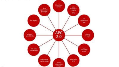
When thinking about modularity, visualize Lego brand bricks. Every brick and element has a standardized means of interfacing with other bricks and elements (See S88.01 Models diagram). This modular construction system, with its standardized interface, allows using and reusing the same parts to build almost anything you can imagine.
Modularizing a process requires users to:
Define and align the purpose of the module and its components. Almost anything that can be called a system can also be called a module. When developing modules avoid confusing use with purpose . Purpose defines what the equipment does;
Establish the use of each module by defining how it interacts with its neighbors. Is it used stand-alone, shared, or as an exclusive-use module?
Determine if a module can be portable. Can it be (or has it been) duplicated or moved to another process or location? Having processes share designed, tested, and proven modules is the goal of modularity and key to achieving ‘agile’ manufacturing;
Design and define module to take full advantage of equipment capability, even if not every capability is needed for every product;
Define modules to be independent in their abilities. For example, if interlocks, messaging, and alarms are necessary for the module to operate safely and independently, then these should be an integral part of the module;
Ensure modules allow capacity expansion of a process by adding and/or copying existing modules (see module portability);
Give modules ability to minimize or isolate process upsets within themselves; and
Determine the physical process constraints of modules. For example, if multiple tanks use a pump, it must be defined outside the boundaries of any tank.
Until the development of S88.01 the content and organization of control system specifications were as different as the number of persons preparing each request for quote specification. S88 introduced a structure resembling object-oriented methodologies, but does so using process control terms (see S88 definitions).
Processes and process control have always been object-oriented entities. Vessels, pumps, valves, transmitters, and controllers represent physical objects joined together by pipe and wire. When raw materials, chemicals, and energy are introduced, procedures cause objects to move, spin, heat-up, cool-down, and hopefully produce the desired product according to a defined procedure (see PVC process using modular design diagram).
Performing parallel design of the process and control system integrates automation into each equipment entity. For example, P&IDs (piping and instrumentation diagrams) are easier to understand when arranged so control system elements and associated units appear on the same drawing.
Processes have always been made up of objects, but until S88 came along, the methodsto describe objects and procedures was different from industry to industry, andsometimes even from project to project.
Getting started
Generally, the first effort is definition of the physical process, the organization of the process, and its capabilities. Conducted in parallel with development of the PFDs (process flow diagrams), this is a top down exercise where the entire process is defined in general terms and major equipment requirements are identified. Repetitive design ‘passes’ add more and more detail.
Defining physical process entities using a seven-step process will deliver a modular design.
Identify the process cell;
Identify the units within each process cell;
Identify the equipment modules for each unit;
Identify the control modules for each equipment module and/or unit;
Re-evaluate the boundaries of each equipment module;
Re-evaluate each unit’s boundaries; and
Re-evaluate each process cell’s boundaries.
When physical entities are defined, the next step defines procedural requirements using a bottom up approach. Procedural requirements exist for both recipes and equipment. Their independence from, or association with equipment, is where differences exist. Recipe procedures are independent of equipment. When viewed in a hardware/software architecture, recipe procedures reside in batch manager devices and equipment procedures reside in controllers.
Development of procedures should follow a four step, bottom-up order. Users should:
Define operations that are reusable across multiple products;
Define operations used for specific products;
Use operations to construct product-specific unit procedures; and
Use unit procedures to build product recipes.
To permit procedural elements to interact with physical entities some form of ‘phase logic interface’ is needed to define data structures and communication protocols (see Phase logic interface diagram). For some systems, the user needs to write, purchase, or somehow acquire the phase logic interface software. Other system providers have embedded the phase logic interface in their system software.
While the S88 standard (S88.01 and dS88.02) provides additional information, using the methods described above are sufficient for developing a preliminary design and implementation estimate.
Tying procedural and physical entities together is accomplished using phase logic.In some batch systems phase logic is embedded, in others the user must acquire, write, or purchase it.
Testing the methods
To verify how well the described methods work, Control Engineering developed a sample process and sent it to 14 control system vendors who offer batch solutions. The request was for a
Even though the request was for a
A required level of deliverable documentation. A few companies have developed ‘standardized’ documentation deliverables and refine their deliverables (and hours) when they prepare a
Type of hardware and software platforms to be used is important to system integrator’s implementing on multiple platforms;
Startup and/or training support. This was repeatedly mentioned and a few included an estimate of hours ranging from 16 to 300 hours. Estimates for training ranged from 16 to 40 hours; and
Foreign devices, especially those requiring serial interface. These can be complex to integrate, especially if the device has its own operator interface.
There was also concern from the responders of how estimates would be interpreted and presented. The ‘average’ time of seven received, was 694 hours, with another 132 hours needed for startup, training, and administration support activities.
This unscientific survey did not answer the long-running question between DCS and PLC vendors about implementation times. Estimates received show DCS implementations take slightly less time, but not in every case.
Refining afine an estimate to ±10% (or better) is through a contractual arrangement to develop detailed functional specifications. A tangible benefit of this approach is if the project continues, the assembled project team remains together through implementation, training, and startup.
Most responders listed similar needs for information to prepare a batch process implementation estimate, and their needs closely match S88’s models and terms. A few surprises include a desire to receive detailed recipe information, site and building plans, and enterprise integration requirements. Most responders also want an I/O list, but added it was of minor importance.
The lesson learned-to achieve an agile process automation facility, prepare documents using the methods described above, but before sending them out for quotes, ask what other documents should be included.
S88 definitions
S88.01’s goal is to establish a common set of terms and models that can be used to communicate process automation requirements. Definitions for the eight blocks shown in the S88 Models diagram are:
Physical models
Process cells (sometimes called trains) define a logical grouping of equipment necessary to produce one or more batches, though not necessarily a final product. Defining process cells makes production scheduling easier. Considerations when defining process cells include:
Establish clear boundaries;
Functions performed must be consistent regardless of what product is being produced;
Interact with other process cells minimally and when necessary, conducted at the same or higher entity level i.e., process cell to process cell; and
Maintaining consistency so operators interacting with similar entities do so naturally and without confusion.
Units are a collection of equipment and control modules in which major processing activities, such as react, distill, crystallize, make solution, etc., can be conducted. Unit characteristics:
Operate on only one batch at a time;
Cannot acquire another unit; and
Operate independent of other units.
Equipment modules are functional groups centered around a piece of processing equipment that carry out defined activities, such as header control, dosing, weighing, jacket service management, scrubber control, etc. A collection of control modules can become an equipment module if the collection executes one or more equipment phases.
Control modules are the lowest grouping of equipment capable of carrying out basic control. For example, solenoids and limit switches combined can form Off/On valve control modules, and transmitters and valves can be combined into PID control modules.
Procedural models
Phases accomplish a specific process-oriented task, can be executed sequentially or in parallel, can be self-terminating, and need to account for exception condition handling. When defining phases, a few of the considerations include:
Consistent use of predefined states, such as holding, held, restarting, failing, etc.;
Consistent use of predefined commands, such as hold, stop, abort, etc.;
Definition of the modes for each phase, and how the phase will respond to each mode. For example, is a single-step mode needed for troubleshooting?
Definition of exception handling and recovery mechanism’s; and
Data collection of phase-related activities.
Operations are independent processing activities that usually result in a chemical or physical change in the material being handled. Operations include the instructions necessary for the initiation, organization, and completion of activities such as prepare reactor, charge, heat, cool, react, etc.
Unit procedures provide a strategy for carrying out operations and methods in a contiguous manner within a single unit. A unit procedure can execute concurrently on different units.
Procedures are the strategy for carrying out batch activities within a process cell. Procedures, such as clean-in-place, do not always produce a product or a product intermediate.
For more information on S88.01 definitions contact ISA at (919) 549-8411.