PID: Proportional-integral-derivative controllers may be ubiquitous, but they’re not perfect. Consider how deadtime affects integral action.
In proportional-integral-derivative (PID) control methods, the actions of the integral, the “I” term in PID, can be particularly problematic because the controller’s integrator continues to build up an ever-increasing control effort so long as an error remains between the measured value of the process variable and the desired setpoint. Look at the related challenges and advice that follow for more practical help to fix PID.
Previous installments of this series—”Fixing PID, part 1” (Control Engineering, November 2012) and “Fixing PID, part 2” (Control Engineering, May 2014) linked below, online—have examined the limitations of PID controllers and the various patches engineers have developed to fix them.
With a PID controller, a particularly aggressive integral action can cause the controller to oscillate back and forth, hunting in vain for a control effort that will force the process variable to match the setpoint. The integral action also has trouble dealing with a process that does not respond immediately to the controller’s efforts. The longer the delay, or deadtime, the greater the integrated error becomes before the process variable starts to move. That in turn causes the integral action to work harder and harder, potentially to the point of doing more harm than good.
Rate-limited actuators
Fortunately, these tend to be especially obvious problems that an experienced control engineer can spot and fix readily, either by scaling back the integral action or by modifying the process to be easier to control. A more insidious issue arises when the actuator responsible for applying the controller’s efforts to the process is rate-limited.
A rate-limited actuator is one that can’t act as fast as the controller wants it to, usually as a result of mechanical limitations. A valve, for example, can only open or close as fast as the actuator can move the stem. It tends to fall behind when the controller gives it a command to open or close too rapidly.
The actuator’s rate limit will in turn limit how fast the process variable can change, leaving a sustained error between the process variable and the setpoint. Just as when deadtime prevents the process variable from changing at all, the integrated error will continue to grow as will the integral action. That makes matters worse and worse as the actuator falls further and further behind. This reset windup effect is less pronounced when caused by rate limiting rather than deadtime, but unstable oscillations in the process variable result either way, as explained in the “Effects of deadtime and a rate-limited actuator” diagram and sidebar at the bottom of this article.
The insidious part is that the effects of a rate-limited actuator don’t always show up immediately. If the controller’s commands are fast but small, the actuator might still be able to keep up for a while. The controller might even be able to maintain the process variable at the setpoint for years, so long as any disturbances that move the process variable off its mark happen to remain modest. But if a large enough disturbance comes along requiring a commensurately large control effort, the integral action will start to wind up, and hunting will ensue unexpectedly.
External reset to the rescue
Fortunately, there are three simple fixes for a rate-limited actuator. The most obvious is to replace the sluggish actuator with a faster one capable of implementing the controller’s commands in a timely manner. Continuing the example, sometimes cleaning the stem of a gunked-up valve to reduce rate-limiting friction is enough.
Conversely, the integral action can be slowed to the point that the controller no longer asks for impossibly fast actuator moves when reacting to large disturbances. However, doing so also retards the controller’s reaction to small disturbances that aren’t really a problem.
Arguably the most effective solution is external reset. An external reset function modifies the rate at which the error is integrated so that the speed of the integral action matches the speed of the actuator. The result is a controller that seems to know just how fast it can afford to push the actuator. External reset can also combat other forms of reset windup no matter how they are caused. Part 1 of this series discusses that phenomenon in greater detail.
Integrating processes
A PID controller’s integral action can also cause unstable oscillations when the controlled process itself acts as an integrator. Consider, for example, the level of water in a tank equipped with an inflow and an outflow as described in “Fundamentals of integrating vs. self-regulating processes” (Control Engineering, December 2014). Every drop that enters without being removed accumulates in the tank, causing the level to rise. The tank integrates its input (the net inflow minus outflow) to generate its output (the tank level).
The integral action embedded in a PID controller employs a purely mathematical integrator to perform the same conceptual function. It sums all past values of the error between the process variable and the setpoint to generate a numerical output that increases as long as the process variable is less than the setpoint and decreases as long as the process variable is greater than the setpoint. This integrated error is multiplied by a gain to generate the integral action’s control effort.
Both the tank and the controller’s integrator react to step changes in their inputs by ramping up their outputs as shown in Figure 2, “Back-to-back integrators.” Connecting the two in series as shown in Figure 3 leads to an exponential increase in the tank’s output when the controller’s input is stepped up. This behavior is typical of back-to-back integrators, which is why integral control applied to an integrating process often leads to unstable results.
Loop tuning tradeoffs
As in the case of rate-limited actuators and back-to-back integrators, many of the patches that have been proposed to fix PID problems involve configuring the controller to be less aggressive in reacting to errors between the process variable and the setpoint. Unfortunately, that configuration operation, known as loop tuning, can itself be a problem.
In fact, loop tuning is arguably the most difficult aspect of designing a PID controller because the appropriate choices for the P, I, and D parameters required to achieve just the right mix of the three actions are rarely obvious. Even experienced control engineers can find it challenging to observe the controller in action and decide which of those parameters needs to be increased or decreased, let alone by how much.
For example, the derivative action can be used as a brake to prevent rapid changes in the control effort as the controller is trying to bring the process variable in for a landing right on the setpoint. Without it, a controller with especially aggressive integral and proportional action can drive the process variable towards the setpoint so rapidly that it overshoots. That in turn will cause the controller to overcorrect in the opposite direction, potentially overshooting back and forth again and again.
On the other hand, the derivative action also gives the process an immediate kick at the outset of a disturbance response. That kick can help drive the process variable in the right direction without waiting for the integral and proportional actions to ramp up their efforts. However, if the derivative action is tuned to be especially aggressive for the sake of braking at the end of a disturbance response, it can also be too aggressive in kicking the process at the beginning. This can cause overshoot too, particularly when the controlled process is particularly sensitive to the controller’s efforts.
Loop tuning software helps
Fortunately, innumerable formulas and software packages have been developed to facilitate loop tuning. Control engineers do not need to rely solely on qualitative observations of the controller in action. They can accomplish a great deal with quantitative measurements of the process’s open and closed-loop behavior. See “Loop tuning fundamentals” (Control Engineering, July 2003).
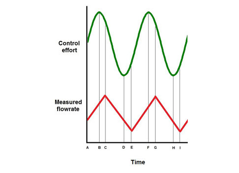
Effects of deadtime and a rate-limited actuator
A PID controller can cause hunting when its actuator is subject to deadtime and/or rate limitations. In this flow control example, an especially aggressive controller is using a rate-limited valve to maintain the flowrate downstream. At time A, it commands the valve to open rapidly in an attempt to combat a drop in the flowrate cause by a load disturbance. The valve responds as fast as it can between times A and B, but not as fast as the controller expects. Thinking that its efforts have been inadequate, the controller starts to push the valve even harder, but to no avail. At time B, it reverses course after detecting that it has overcorrected for the original disturbance. The actual flowrate begins to drop as soon as the controller commands the valve to start closing, but since the flowmeter is located some distance downstream, the controller continues to see the flowrate increasing until time C. By then, the controller has already begun to undershoot the setpoint in the opposite direction. This sequence repeats at times D and E, F, G, H, and I, etc. Courtesy: Control Engineering
– Vance VanDoren, PhD, PE, is a Control Engineering contributing content specialist. Reach him at [email protected]. Edited by Peter Welander, Control Engineering, [email protected].
Key concepts:
- PID control can be found everywhere, but few understand its peculiarities.
- Understanding how it works can help unravel problems and improve tuning.
Consider this
How many of your control loops are open? How much more efficient could you be with closed-loop control?
ONLINE extra
See PID articles, Fixing PID, Parts 1 and 2 linked below.
Click here to register for the PID Digital Report for more PID articles.