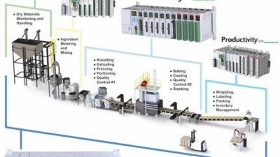
Back to Basics: Describe your process to preserve the process engineer knowledge for the future. To program the process controller, programmable logic controller (PLC), or distributed control system (DCS), follow these steps and methodology, starting with understanding the requirements and documenting in a requirements document, also called a BPO, CFE, an FS, or URS.
Describe a process in such a way as to preserve the process engineering knowledge for the future. To program the process controller, programmable logic controller (PLC), or distributed control system (DCS), a few steps must always be followed. Sometimes these steps are done orally, and in other cases, where a controlled environment exists, these are done with written documents following strict procedures. Whatever methodology is used, the first step is always “understand the requirements.” When control systems’ programmers are asked to write/modify a program to control the process, the first thing they should request is a written document that describes the requirements.
Names vary for requirements documents
This requirements document has different names in various industries. Under good automated manufacturing practice (GAMP), common in the FDA regulated industries, it is called user requirement specification (URS). In batch industries it is called basic process operations (BPO), and in continuous plants it is usually called conceptual functional specifications (CFS) or simply functional specifications (FS).
A BPO document is a first step in creating a control system for controlling the (production) process. The BPO document is a generic document independent of the platform upon which it will be implemented. The BPO document should be written with enough details so a (process) control engineer / programmer would be able to use it to write a detailed functional specification (DFS) document. The DFS is a translation of the BPO document into a specific type/product of control system. Reading the DFS enables the control engineer/programmer to write/build the control software/application for controlling process operation. [subhead]
Two BPO answers
The BPO document should answer two basic questions: 1) How should the process behave under normal operations? and 2) What actions should be taken in case of unforeseen events?
The BPO document is a process state/operations description, and it is mostly implemented in the process controller and not in the operator interface (HMI). One of the most important features is that it documents the process operation as designed and seen through the eyes of the process engineer and maintains the process knowledge in it for future readers and users of the operational unit.
Definitions
A process operation is a detailed description of multiple transitions between states.
A state is a specific condition of the equipment, usually at rest or steady state condition, and a transition is a shift of the equipment between two states.
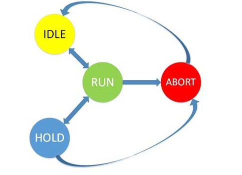
For simplification, the following basic states of the equipment will be described:
- IDLE (initial state)
- RUN
- HOLD
- ABORT
For further details on the use of these states in the batch industry, the reader is referred to the S88 standard.
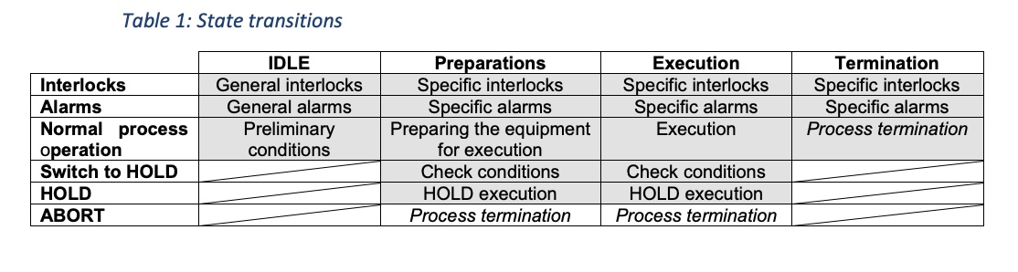
Each process operation has four operational stages: 1) IDLE, 2) Before the execution, 3) Execution, and 4) Termination. The possible transition between these states is described in Drawing 1 and Table 1.
BPO Chapters
The BPO document should contain the following chapters:
1. The unit
1.1. P&ID / process sketch
1.2. List of main/relevant equipment and all instruments
2. The process
2.1. General process description (in words)
2.2. Process parameters
2.3. General interlocks and alarms
3. The operation
3.1. Preliminary conditions
3.2. Detailed process description
3.3. Hold execution
3.4. Abort execution
1 The unit
1.1 P&ID / Process sketch
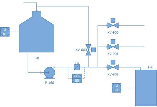
The first thing that we need to do when defining a process is to define its physical limits/boundaries. In this example, refer to the simplified equipment units’ arrangement (Drawing 2). It contains a clean water source tank (T-8), a pump (P-160), 1 circulation valve, 3 valves manifold, and 1 recipient tank (T-9). The operation under control will be the transfer of water from T-8 to T-9.
1.2 List of main/relevant equipment and all instruments
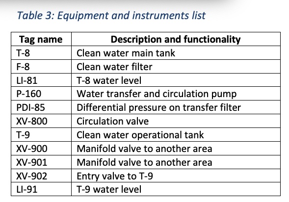
As it is our main goal to preserve our knowledge and explain why we are asking for a specific action to be performed, we must be as clear as possible. We need to make sure that we identify all the relevant equipment and instruments that are involved with our process operation. Later in the document, we will be referring to items ONLY from this list.
If the process operation is generic, the tag names that will appear in the table will be generic and there will be a table to convert between the generic name and specific name for each piece of equipment in the following format. See Table 2.
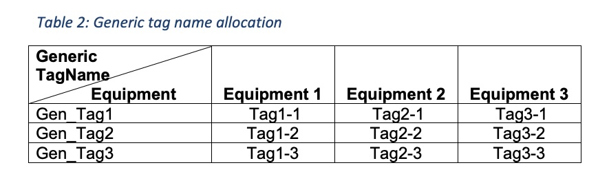
Table 3 lists the equipment for the current process operation.
2 The process
2.1 General process description (in words)
Tank T-8 contains clean water main storage. To keep the water clean, storage tanks are circulated constantly through a filter F-8. Occasionally, as process operations require, we need to transfer clean water to other locations at the site. During a transfer we should not circulate as we want the water to be sent at the shortest time possible to the operational area. When transferring water, only one of the manifold valves can be opened at a time in order to prevent backflow and possible contamination of the manifold and water in the main tank T-8. During the transfer, water does not enter into the clean water main tank T-8.
This BPO will deal with water transfer from T-8 to T-9.
2.2 Process parameters
All parameters that are relevant for the current process operations are listed in this chapter. There are three kinds of parameters.
-
The first is an external parameter. It is related to the process operation’s functionality and serves as the interface between the equipment and the entity that manages it, whether it is an operator or a higher-level automated process operation. Each external parameter has two values that should be kept in historical records. The target value (SP) and the current value (PV), which is dynamic and changes as the process operation is executed.
-
The second is an internal parameter that is related only to the process operation setup. It contains information about the equipment itself.
-
The third parameter is an internal parameter that is used only during the process execution and is not saved or monitored after the execution.
A parameter is not changeable after the process operation has started its execution.
The parameters for our process are detailed in Table 4.

2.3 General interlocks and alarms
This section lists the interlocks and alarms that are active all the time. An interlock/alarm is being activated after an issue related to the core operation of the process operation had been identified. Every interlock that is being activated during the execution of a specific phase/step indicates a process operation problem, and it will automatically cause the process execution to switch to a HOLD state. Every alarm being generated indicates a possible problem developing, and therefore, in each case, we must define if the alarm should automatically switch the process operation execution to a HOLD state.
Each interlock/alarm must be defined using the following items:
- Purpose of the interlock/alarm
- How this state is identified
- Corrective action.
The methodology of defining an interlock or alarm is as follows:
[Level ] Verbal interlock/alarm title
Alarm — corrective action by a person
[1] To prevent (Describe the situation that may happen), [2] which is identified by (describe the measurement), (Tagname), in state (PV) (for a duration longer than xx seconds), [3] generate alarm at [level]. [4] Define operator action. ([5] Switch to a HOLD state.)
Interlock – corrective action by an automated control system
[1] To prevent (Describe the situation that may happen), [2] which is identified by (describe the measurement), (Tagname), in state (PV) (for a duration longer than xx seconds), [3] set (description of equipment), (Tagname), to SP.
2.3.1 Interlocks
2.3.1.1[Level 2 – Medium] Empty water tank T-8
[1] To prevent a mechanical failure of the water transfer and circulation pump P-160, [2] when the water level in T-8 tank, identified by LI-81, is below 10%, [3] Set the command to the Water Transfer and Circulation pump P-160 to STOP.
2.3.1.2 [Level 2 – Medium] Clogged clean water filter F-8
[1] To prevent a mechanical failure of the water transfer and circulation pump P-160, [2] when the pressure drop on F-8 filter, identified by PDI-85 is above 2.5Bar for more than 60 seconds, [3] Set the command to the water transfer and circulation pump P-160 to STOP.
2.3.1.3 [Level 2 – Medium] All valves closed
[1] To prevent a mechanical failure of the water transfer and circulation pump P-160, [2] when all exit valves are closed, identified by XV-800, XV-900, XV-901, and XV-902 states are all CLOSED for more than 60 seconds, [3] Set the command to the water transfer and circulation pump P-160 to STOP.
2.3.1.4 [Level 3 – Low] Receipt tank, T-9, full
[1] To prevent an overfill of the receipt tank T-9, [2] when the tank level is high, identified by LI-91 is above 90%, for more than 10 seconds, [3] Set the command to the water filling valve, XV-902, to CLOSE.
2.3.2 Alarms
2.3.2.1 [Level 2 – Medium] Clogged clean water filter F-8
[1] To prevent a dirt accumulation in the clean water main tank, T-8, [2] when the pressure drop on F-8 filter, identified by PDI-85 is above 1.5Bar for more than 60 seconds, [3] generate an alarm level 2. [4] Operator action: The operator should verify why the filter is clogging and monitor its operation in the next 3 hours to verify that there is no problem with dirt arriving and accumulating in the T-8 tank.
2.3.2.1 [Level 2 – Medium] Receipt tank, T-9, is nearly empty
[1] To prevent the operation from being stuck without water, [2] when the water level in T-9, identified by LI-91 is below 50%, [3] Generate an alarm level 2. [4]Operator action: The operator should verify that there is enough water in the clean water main tank, T-8, and that the process is ready to perform a transfer of the water to the clean water operational tank T-9 within the next 30 minutes.
3 The operation
In the following BPO chapter the actual process operation is described.
3.1 Preliminary conditions
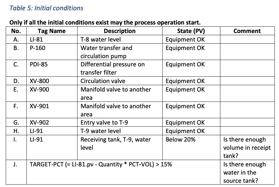
This chapter defines the initial conditions that should exist to start the operation. The status of these conditions may, and often do, change after the operation begins. The conditions must be met only before the operations starts. Table 5 shows initial conditions.
All conditions must be met with AND logic.
If initial state logic conditions are more complex, then the logic should be more clearly defined. An example of a more complex logic is shown in Drawing 3.
3.2 Detailed process description
3.2.1 General Every process operation execution is built from three parts:
- Preparations
- Execution
- Termination
Each operation description is a set of steps sequence-built from the pair (1) “Action” (2) “Wait for.” Each pair is called a step. In cases where many steps are involved, it is considered a good practice to number them. This eases tracking and tracing.
3.2.1.1 Action Each action in the process description must contain a detailed description of the action to be done simultaneously in the following format.
- Set (Equipment functional description), (Tagname1) to (SP) state
- Set (Equipment functional description), (Tagname2) to (SP) state
- Set (Equipment functional description), (Tagname3) to (SP) state
3.2.1.2 Wait for
Each waiting contains any combination of the following wait conditions in the following formats.
- Wait for (Equipment functional description), (Tagname1) to be in (PV) state
- Wait (SP) seconds
- Wait for Operator reply
In some cases we cannot wait for the process execution to pause for the specified condition. This might be due to an equipment malfunction, process behavior, or any other reason. For each waiting we must define if this wait can be bypassed by the operator/supervisor/engineer/… according to the levels defined by the organization. The following format should be used:
- Yes/No – Wait can be bypassed by Operator
- Yes/No – Wait can be bypassed by Supervisor
- Yes/No – Wait can be bypassed by Engineer
3.2.2 Preparations
3.2.2.1 General
In the preparations phase we prepare the process for the execution of the main task of the BPO. Until this phase is complete, we have not yet started the main operation and we can still abort the process with minimal effect on the actual production. As noted in Table 1, we need to specify for each phase its specific interlocks and alarms. This is why each phase has three parts: (1) Actions, (2) Specific Interlocks, and (3) Specific Alarms.
1. Actions
1.1 Step 1
1.1.1 Step 1 Action
1.1.2 Step 1 Wait
1.2 Step 2
1.2.1 Step 2 Action
1.2.2 Step 2 Wait
1.3 Step 3 (Last step in the Preparations phase)
1.3.1 Step 3 Action
1.3.2 Step 3 wait (This wait finishes this phase and the execution moves to the second phase of the process operation execution.)
2. Specific interlocks
Interlocks that are specific ONLY to this phase should be included in this section. The interlocks are to be described in the same format as defined in section 2.3, General interlocks and alarms.
3. Specific alarms
Alarms that are specific ONLY to this phase should be included in this section. The alarms are to be described in the same format as defined in section 2.3, General interlocks and alarms.”
3.2.2.1 Actions
3.2.2.1.1 Step 1 – Close all valves.
3.2.2.1.1.1 Set all outlet valves, XV-800, XV-900, XV-901, XV-902, command to CLOSE.
3.2.2.1.1.2 Wait for all outlet valves, XV-800, XV-900, XV-901, XV-902, PV state to be CLOSED.
3.2.2.1.1.3 This step cannot be bypassed.
3.2.2.1.2 Step 2 – Start pump and build pressure.
3.2.2.1.2.1 Set the water transfer and circulation pump, P-160, command to RUN.
3.2.2.1.2.2 Wait for water transfer and circulation pump, P-160, PV state to be RUN, then wait for PUMP_START seconds.
3.2.2.1.2.3 This step cannot be bypassed.
3.2.2.1.3 Step 3 – Start the water transfer.
3.2.2.1.3.1 Set the entry valve to T-9, XV-902, command to OPEN.
3.2.2.1.3.2 Wait for the entry valve to T-9, XV-902, PV state to be not CLOSED. (This wait finishes this phase and the execution moves to the second phase of the process operation execution.)
3.2.2.1.3.3 This step cannot be bypassed.
3.2.2.2 Specific interlocks
There are no specific interlocks for this phase.
3.2.2.3 Specific alarms
3.2.2.3.1 [Level 1 – High] Fault in any equipment
[1] To prevent a situation where the program can no longer control the process
[2] When any of the following related devices is not in an “OK” status:
- Outlet valves, XV-800, XV-900, XV-901, XV-902
- Water Transfer and Circulation pump, P-160
- T-8 water level, LI-81
- T-9 water level, LI-91
[3] Generate an Alarm Level 1.
[4] Operator action: The operator should check the cause of the alarm and resolve the situation.
[5] Switch the process execution to HOLD.
3.2.3 Execution
This is the main execution phase of the process.
3.2.3.1 General
This phase first action is “wait for” as the last action/wait that was done in the preparation phase took us to this phase.
3.2.3.2 Actions
3.2.3.2.1 Step 1 – Wait for the amount to be transferred.
3.2.3.2.1.1 Wait for the clean water main tank T-*, water level, LI-81, PV will be less than TARGET-PCT. (When this waiting finishes, this phase and the execution move to the third phase of the process operation execution.)
3.2.3.2.1.2 This step can be bypassed by the operator.
3.2.3.3 Specific interlocks
There are no specific interlocks for this phase.
3.2.3.4 Specific alarms
3.2.3.4.1 [Level 1 – High] Fault in any equipment
[1] To prevent a situation where the program can no longer control the process
[2] When any of the following related devices is not in an “OK” status:
- Outlet valves, XV-800, XV-900, XV-901, XV-902
- Water transfer and circulation pump, P-160
- T-8 water level, LI-81
- Differential pressure on transfer filter, PDI-85
- T-9 water level, LI-91
[3] Generate an Alarm Level 1.
[4] Operator action: The operator should check the cause of the alarm and resolve the situation.
[5] Switch the process execution to HOLD.
3.2.3.4.2 [Level 2 – Medium] Multiple valves not closed
[1] To prevent a situation where the water is being sent to more than one destination
[2] When any of the outlet valves, XV-800, XV-900, XV-901, is not in a “CLOSED” state
[3] Generate an alarm level 2.
[4] Operator action: The operator should check the cause of the alarm and resolve the situation.
[5] Switch the process execution to HOLD.
3.2.3.4.3 [Level 3 – Low] Not enough water to transfer
[1] To prevent a situation where there may not be enough water in the clean water main tank, T-9
[2] When the T-8 water level, LI-81, PV is below 30%
[3] Generate an alarm level 3.
[4] Operator action: The operator should verify that there is enough water in the tank to complete the operation.
3.2.3.4.4 [Level 3 – Low] Clogged clean water filter F-8
[1] To prevent a situation where the process may stop due to high dirt concentration in the water
[2] When the pressure drop on F-8 filter, identified by PDI-85 is above 1.0Bar for more than 30 seconds,
[3] Generate an alarm level 3.
[4] Operator action: The operator should verify that there is no fast pressure buildup and the process operation will be able to complete the execution. When the execution terminates, the operator must verify the reason for the increase in the pressure in PDI-85.
3.2.4 Termination
3.2.4.1 General
3.2.4.2 Actions
3.2.4.2.1 Step 1 – Close transfer valve.
3.2.4.2.1.1 Set the entry valve to T-9, XV-902, command to CLOSE.
3.2.4.2.1.2 Wait for the entry valve to T-9, XV-902, PV state to be CLOSE.
3.2.4.2.1.3 This step cannot be bypassed.
3.2.4.2.2 Step 2 – Stop the water pump.
3.2.4.2.2.1 Set the water transfer and circulation pump, P-160, command to STOP
3.2.4.2.2.2 Wait for water transfer and circulation pump, P-160, PV state to be STOP.
3.2.4.2.2.3 This step cannot be bypassed.
3.2.4.3 Specific interlocks
There are no specific interlocks for this phase.
3.2.4.4 Specific alarms
There are no specific alarms for this phase.
3.3 Hold execution
3.3.1 General
The Hold section has three parts.
1. Hold execution actions
2. Resume from HELD conditions
3. Resume from HELD actions
Steps and conditions in this chapter are written in the same way as defined above in the appropriate sections.
3.3.2 Hold execution actions
3.3.2.1 General
Hold execution phase always finishes in a temporary safe state of the process and in conditions that will allow the process to resume its execution.
3.3.2.2 Hold actions
3.3.2.2.1 Step 1 – Close transfer valve.
3.3.2.2.1.1 Set the Entry valve to T-9, XV-902, command to CLOSE.
3.3.2.2.1.2 Wait for the Entry valve to T-9, XV-902, PV state to be CLOSE.
3.3.2.2.1.3 This step cannot be bypassed.
3.3.2.2.2 Step 2 – Stop the water pump.
3.3.2.2.2.1 Set the water transfer and circulation pump, P-160, command to STOP.
3.3.2.2.2.2 Wait for water transfer and circulation pump, P-160, PV state to be STOP.
3.3.2.2.2.3 This step cannot be bypassed.
3.3.3 Resume from HELD conditions.
The conditions are almost the same as the process initial conditions.
To be able to resume the operation, all conditions A thru H must exist. (AND)
3.3.4 Resume from HELD actions
3.3.4.1 General
If there is a specific sequence to be done before a process can resume, the steps are written in this section. In most cases the resume actions are the same as the preparation phase excluding any calculations that were made based on initial conditions.
When these actions are complete, the target phase/step where the process execution will resume from must be defined.
3.3.4.2 Resume actions
Resume actions are identical to preparations phase.
After resume actions, continue the process operation execution from phase execution step 1.
3.4 Abort execution
There is no automatic switch to this phase. It is done solely by a direct order from the operator. The actions of the abort phase are generally identical to those done at the last normal phase of the operation as defined in section 3.2.4 Termination above.
After an abort is executed, the process is not allowed to start automatically and an operator Reset would be required to indicate that all conditions are back to normal.
– Oren Yulevitch is chief executive officer of Oren Yulevitch Consulting Services. Edited by Mark T. Hoske, content manager, CFE Media, Control Engineering, [email protected].
ONLINE
This article online tutorial includes additional information: five tables, along with details on BPO chapters, process description, interlock and alarms, operations, conditions, and conditions for logic.
Key concepts
- Documenting process knowledge is an investment in the future.
- Requirements documents have various names: URS, BPO, CFS, and FS.
- Basic process operations documentation helps with programming.
Consider this
When undocumented process knowledge walks out the door or retires, what’s the cost?