Although VFD manufacturers have made many advances in terms of ease of use, some users still find programming and monitoring with a 2-inch display tedious. This is where VFD programming and monitoring software comes into play.
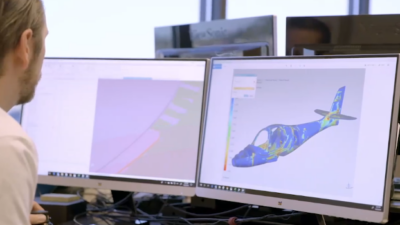
Variable frequency drives (VFDs) have been around for decades now. During their infancy, programming involved moving jumper blocks and adjusting potentiometers. As time passed, technology evolved (see Figure 1). Although seven-segment light-emitting diode (LED) keypads began to emerge, programming and monitoring was easier but still somewhat cryptic. Eventually, full-text liquid-crystal display (LCD) keypads became the norm. These keypads feature multiple lines of text that can be displayed in many languages. Navigation is intuitive and the display can be customized to display the most useful parameters. Although VFD manufacturers have made many advances in terms of ease of use, some users still find programming and monitoring with a 2-inch display tedious. This is where VFD programming and monitoring software comes into play.
Making programming easier
The benefits of using VFD software can make startups, programming, monitoring, and even troubleshooting much easier. Each device and equipment manufacturer has its own set of parameters, monitors, and factory defaults. When working with more than one device on a daily basis, any tool that will eliminate the need for remembering these functions, parameters, and values makes a big difference.
VFD software allows users to search through all parameters and monitors with an active search function. Instead of remembering that parameter "C1-01" is the acceleration time and hunting through the keypad or technical manual to find this, searching for "acceleration" in the search bar will display the matching parameter.
Changing the aforementioned acceleration time is equally easy. Simply clicking on the parameter, entering the new value, and then clicking "Write" changes the parameter nearly instantaneously. There is no more need for multiple keystrokes on the keypad. This function is great for changing one parameter at a time. But what about changing multiple parameters at once to make commissioning and startups as efficient as possible?
VFD startup can be streamlined by using what some software programs call an "application wizard," which takes the guesswork out of VFD application programming. Typically, the wizard asks for information, such as control method, duty, motor data, and control sources. In addition, digital inputs/outputs (I/O), speed limits, and auto-restarts can be configured.
The key benefit of the wizard is that users do not need to think too much about which of the more than 1,000 available parameters. On average, most VFD applications consist of less than 20 modified parameters. Most of them are addressed when using the wizard. After selecting the proper parameter settings in the wizard, the changes are written to the drive in one final step.
Back it up
Writing all of the parameters on the cabinet door with a marker is no longer necessary. Parameter sets can be saved and stored indefinitely on a PC as a backup. These parameter sets are called projects. Users can save as many projects on the PC as the hard drive will allow. It’s a good idea to make a project containing a handful of useful go-to parameters. Project files can be shared with colleagues easily. In some VFD software packages, there are "share" and "export" buttons sprinkled throughout the program. These are convenient for sharing a list of parameters with customers and colleagues or when seeking technical assistance from the VFD manufacturer.
Be prepared
Preparation is one of the most important steps to take when operating in the field. For example, if a system integrator is contracted to provide VFDs with other automation and motion-control equipment, VFD programming software that includes an offline mode can be used as a preparation tool by setting up an offline project with all of the parameter settings programmed ahead of time. When it is time to program the VFD, simply connect it and write the program. This can greatly reduce startup times and can make engineers look even more like experts in the field.
Local and remote monitoring
The most common method for connecting a VFD to a PC is with a universal serial bus (USB) connection. This is the quickest and easiest method because it is considered to be plug-and-play. This local VFD connection is great for quick programming and monitoring. But what about connecting to a drive over long distances, such as on the other side of a manufacturing facility, college campus, or even the other side of the country?
Many VFDs include a networking option. The drive can be configured with an interface, such as an EtherNet/IP card, which allows software to connect to the VFD on the network. A "scan drive" function will scan the local network for any VFDs that may be connected. After selecting a VFD and connection, the functions and features are available through the software even though the drive may be physically located elsewhere. This can save many programming hours as well as the time it takes to walk back and forth across long distances to get to the VFD.
For VFDs installed in remote or rural locations, an Ethernet/IP or cellular connection module can be installed. This module can connect the VFD to the cloud, which allows for programming, monitoring, and VFD status notifications to be emailed or texted. In many cases, the software on these modules supports smartphone connections. This feature is rapidly becoming the industry standard for remote monitoring and programming applications.
Monitoring
VFDs are no longer limited to providing only speed, current, and voltage monitors. I/O status, torque reference, power consumption, analog signal levels, and fault history, and so on can be monitored as well. Access to these monitors allows users to be detectives by piecing together values/parameters from the monitor feature when troubleshooting operation issues or faults.
These aforementioned monitors can be displayed in numerous formats. A status panel displays the digital I/O terminal status. Up to eight additional monitors can be selected to be displayed in the monitor pane, whereas the keypad can display only three at a given time (see Figure 2). Also available in the status panel is the ability to view the 10 most recent faults under the "fault history" tab. Take advantage of the "fault trace" to pursue what occurred when the VFD faulted. Think of the fault trace as a snapshot of what the VFD was doing when the fault occurred. Important values, such as frequency, voltage, current, and dc bus level are recorded.
Another easy-to-read monitor display is the "monitor panel." The monitor panel can display up to four different monitors selected by the user. Signal levels can be displayed on a simulated analog gauge, sliding scale, trend, or LED-style panel. All levels and values are displayed in real time, allowing key insight into the VFD’s current operation (see Figure 3).
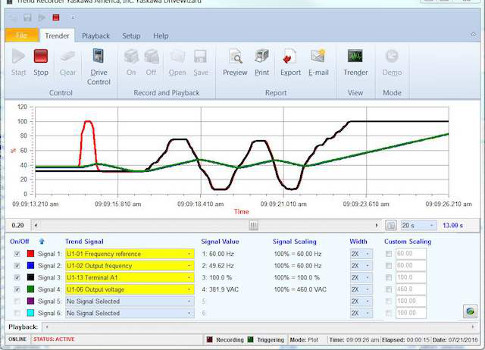
The final monitoring tool is the "trender." The trender tool consists of six selectable signals that display real-time signal level on a graph (see Figure 4). The trends can be recorded in the VFD software and saved for future reference or for sharing with others. Edge triggering is possible for any of the six signals by specifying a trigger level and selecting if the trigger should occur on the rising or falling edge. Trends also can be exported as comma-separated-variable data for use in Microsoft Excel.
The industrial automation industry strives to minimize downtime. It depends on fast and reliable commissioning of new equipment, and a constant flow of monitored data from that equipment. VFD software is a necessary tool to ensure these criteria are met.
Steven Peterson is a technical training associate at Yaskawa America Inc., Waukegan, Ill.