Building a controller has never been easier—or more confusing. This tutorial guide can help determine which motion control architecture to use. See tables, diagrams, and link to video.
Designing a machine controller is all about architectural choices. To build a motion controller that provides precision motion control, first determine where to locate the amplifiers (drives), whether to use a network, and if it’s possible to build the whole controller on one card.
The answers to these questions depend almost entirely on five factors:
- How many machines will be manufactured over the production lifetime?
- Are there specific requirements for the shape, size, and connection method for the controller?
- What is the power range of the motors?
- What is the nature of the machine’s path planning and motion synchronization?
- How critical is time-to-market?
With an eye toward these five questions, the following information will survey the major motion control architectures in use today.
Architecture 1: Off-the-shelf motion cards
The first major architecture for machine controllers is shown in Figure 1, and will be a familiar form to many readers. In this architecture, a purchased off-the-shelf motion card connects to external amplifiers, which accept +/- 10 V analog signal input and control torque or sometimes velocity of the motor.
The machine controller consists of one or more of these dedicated motion cards, motor amplifiers that connect to the motion cards, and a host computer (most often a PC) that holds the user code that controls overall machine behavior and user interface management.
The main choices to make when using this approach are the motion card’s connectivity to the host and the card’s form factor. Popular bus formats include PCI, PC/104, CANBus, and Ethernet. Some of these formats, such as the PC/104 bus, more or less dictate the mechanical packaging of the card. The serial bus-connected cards such as CANBus and Ethernet are sometimes called stand-alone cards and come in a variety of shapes and sizes.
Off-the-shelf motion cards have a number of advantages, the primary one being flexibility. The motion controller is independent of the motor power level and often the motor type. For example, if the motion controller outputs a single phase +/- 10 V signal, this can be connected to a dc servo motor amplifier or a brushless dc motor amplifier (as long as the amplifier performs commutation). If the user wants to increase the power of the motor or change the motor type, the motion card doesn’t need to be changed, only the amplifier.
The primary disadvantage of this architecture is wiring complexity and cost. For a typical servo motion axis, there are 15 to 25 wires that connect to and from each motor axis, depending on whether differential signals are used (highly recommended), and whether the controller or the amplifier performs commutation. Imagine building a controller for a 10-axis system using this approach. It would require bundles carrying hundreds of wires through the machine, a complex, costly, and potentially failure-prone design.
Another disadvantage is that the form factors of the cards purchased off the shelf are generally more complicated to service. Did the motion card have the problem? Was it the amplifiers? Is the problem in the cabling? More parts to the machine controller mean more areas to evaluate if there is a problem.
New off-the-shelf developments
With rapid improvements in the power density of switching amplifiers, a variation of the standard off-the-shelf motion card has been gaining popularity. Many motion control cards now come with optional piggyback amplifier cards (Figure 2). For example, a 3-axis motion card might be mounted directly with a 3-axis piggyback amplifier card, rather than interfacing via cable to discrete amplifiers.
Another variation of the piggyback amplifier card is a custom interconnect card that includes amplifiers. This may be advantageous because an off-the-shelf card comes loaded with particular connectors, whereas a custom-built interconnect card can have connectors that are optimized for a machine.
Architecture 2: Machine controller cards
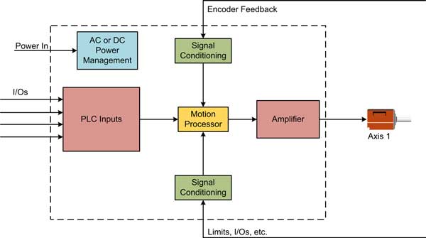
In the integrated machine controller card approach (Figure 3), a microprocessor holds the machine application code; generally, a separate motion controller IC, also called a motion processor, generates profiles, does servo loop closure, and manages the time-critical elements of axis control.
Machine controller cards may directly interface with the user through buttons or a keypad and screen, or they may be subsystems that receive commands from a host via Ethernet or other network connections.
Many advantages of this approach include easier serviceability since the entire controller card is a simple swap-out, reduced wiring since the amplifiers are onboard, application-tailored form factor and connectors, and lower per-controller cost.
The main disadvantage is more design work compared to an off-the-shelf motion card. Still, one can purchase the motion processor to simplify the task of building a machine controller card. This will be discussed in the next section, as will the question of designing your own amplifier and the power levels available from various amplifier approaches.
Building or buying a motion processor IC
When designing a machine controller card, one must decide whether to purchase a motion processor IC off-the-shelf or to build a motion control IC from scratch by programming a microprocessor or DSP.
Figure 4 shows a picture of a sample IC-based general purpose motion processor IC. These units provide profile generation, servo loop closure, commutation, and a myriad list of time-critical functions such as automatic safety responses, programmable breakpoints, and automatic motion axis management.
The chipset shown provides four axes of control simultaneously, but versions are available from one to four axes. There are a number of vendors of such chip-based products.
Off-the-shelf products come with example schematics for connecting to various encoders and amplifiers, and software packages that help develop the machine by providing motion oscilloscope functions and automatic setup of axes connections.
Buying these chips can save time designing profile generator algorithms and writing code for servo compensation filters. It’s possible to use libraries from the DSP vendor for those functions, but they often need to be tailored for specific applications, and everything will need to be put together with the right timing. Servo update routines should calculate and output their values with metronome-like consistency to minimize unwanted harmonics in the motion output.
The case for starting from scratch
So you would be crazy to work directly with a microprocessor or DSP to do the motion control, right? Not necessarily. There are plenty of cases where writing everything from scratch, or starting with DSP or microprocessor vendor-provided libraries is a good approach.
For starters, the cost of general-purpose microprocessors is usually lower than that of dedicated motion processor ICs. If the volume is high enough, that can become important. Also, if the motion profiles are fairly simple, and the machine controller in question won’t need to be used in a lot of different designs, writing motion code may be the way to go.
When designing a machine controller card (or designing a custom piggyback amplifier card), there are three major approaches on how to provide amplification. The choice depends on the motor type and power level needed. Table 2 provides some useful guidelines for amplification design choices.
Single-chip IC refers to low-cost (about $5 to $15 per axis) solderable ICs provided by major semiconductor vendors. They generally max out at about 150 W. Some of these units can provide current control and some cannot, depending on the motor type.
Solderable module refers to a small unit that costs around $50 to $100 per axis that is the size of a deck of cards or smaller. These items come from a variety of motion control vendors. They provide current control and amplification and can drive to higher power levels of 350 W total output or above.
Discrete design means a switching amplifier circuit with pre-drivers, current sense circuitry, MOSFETs (metal-oxide semiconductor field-effect transistors) or IGBTs (insulated-gate bipolar transistors), and additional control and protection circuitry. Cost per axis for the assemblage of parts is from $15 to $35 per axis.
As a general rule of thumb, unless volumes are very high or space and power requirements are exotic, off-the-shelf components are best for amplification. Look to use single-chip ICs or solderable modules wherever possible.
Architecture 3: Stand-alone motion controllers
Another architecture for building a machine controller is the stand-alone motion controller, also known as intelligent amplifier, or indexer. In this approach, the motion controller is a box, generally rack-mounted or DIN-rail-mounted. These drives are usually but not always single-axis, and are fed with a DC bus voltage; for higher power versions they are fed with AC from the wall. This architecture is shown in Figure 5.
Think of each of these boxes as an off-the-shelf motion card packaged inside a box. However, these products tend to serve specific industries and have specific interfaces to the outside world. The machine that is constructed tends to be physically spread out.
A classic example of such a machine is a factory-scale continuous processing facility, such as a bottling facility or candy manufacturer. Materials move down a line and interact with a large number of motion drives that execute small, simple, local functions such as push, pull, chop, fill, etc. One or more PLCs or PCs provide overall control, but each drive is triggered by local sensors for maximum speed and accuracy as the manufactured item moves past them. To make this work, each local stand-alone motion controller has an indexer or PLC input connector with I/O control bits. These input bits can control functions such as moving to a preprogrammed location or executing a specific CAM profile. Modern variations of stand-alone motion controllers include the ability to download programs to an onboard memory so that each drive can execute an autonomous sequence of actions, such as, "Start the motor at speed x, when signal y goes high then coast to a stop, after that wait for z."
Stand-alone controllers work well when the behavior of each axis is fairly simple and more or less autonomous. In addition, compared to off-the-shelf cards that use external amplifiers, wiring is simplified. Each unit contains one complete functioning single-axis controller, so the wiring used to interconnect a motion card to an amplifier is in the box and out of sight.
The central disadvantage, at least historically, is that stand-alone machine controllers tend to be big, relatively expensive, and use PLC-centered programming languages. This is desirable for some applications, since these units are easy to service and very robust. But if the machine is the size of a car or smaller, this architecture may not be the best option.
Architecture 4: Distributed drives
The final motion architecture uses strings of motion modules known as distributed drives (Figure 6), combining the synchronization ability of multi-axis motion cards with the reduced wiring and increased robustness of stand-alone motion controllers. Distributed drives use a network to communicate with a central host but still have all the standard drive features of profile generation, amplification, and internal ac or dc power management.
Depending on the application, two kinds of distributed drives are used. The first can be referred to as a tightly coupled drive. It uses high-speed and deterministic networks such as SERCOS, EtherCat, or Ethernet/Powerlink. Tightly coupled drives require a motion card or a PC running special software to synchronize and coordinate the motion of each axis. Each drive receives rapid position and/or velocity updates, generally several hundred or even several thousand times per second.
The second type of distributed drive can be referred to as a loosely coupled drive. It uses slower speed networks such as Ethernet, CANBus, and RS-485. Loosely coupled drives are also controlled from the host but utilize more profiling capability in the drive. In this architecture, commands are sent to each drive, such as, "Move the axis to position x using a point-to-point s-curve." Interactions in those drives tend to be more autonomous and use local sensor inputs.
The advantage of distributed drives, whether tightly or loosely coupled, is reduced wiring and increased reliability. Another advantage is scalability. Adding one more axis to a distributed drive network is a simple matter of plugging in another drive. In multi-axis motion card architectures, adding another axis can require a whole new card purchase if a fifth axis must be added to a 4-axis card, for example.
Locating the drive on the motor
An important variation of the distributed drive architecture is locating the drive on the motor itself. This approach eliminates all wiring from the drive to the motor, and therefore has an advantage of connection simplicity.
A challenge area for this approach is that the electronics, when mounted on the motor, will have the added heat output of the motor to contend with, along with whatever vibration environment the motor operation introduces. Bear in mind that if the electronics fail, the entire integrated controller/motor unit must be replaced, which may or may not be workable for the machine and its access points for servicing.
Cost for these all-in-units can be a pro or a con, depending on your application. Cost advantages stem from the reduction of wiring and associated construction cost. Cost disadvantages stem from the fact that electronics that can operate in the demanding physical and heat domain of the motor are tricky to design and package.
Making the final decision
When is one architectural approach used over another? There is no easy answer, and sometimes two architectures can be used equally well for a given application.
In broad terms, for more cost-sensitive applications, it is better to design a card and integrate onboard amplifiers, if possible. It’s helpful to be able to choose specific connectors and set the form factor of the card for the application.
Highly synchronized applications such as machine tools will gravitate toward a tightly coupled distributed drive approach. While not cheap, these drives allow a lot of flexibility in motor type and power range. Don’t forget that this approach still requires a motion control card for overall path generation, or you will use a PC running dedicated g-code software.
A large middle ground of applications, such as medical automation, semiconductor automation, scientific instrumentation, and low-power general automation, can be served by several approaches including off-the-shelf motion cards, custom built machine controller cards, and loosely coupled distributed drives.
Chuck Lewin is the founder and vice president of engineering at Performance Motion Devices (PMD), a vendor of chip-based motion control products.