Automated motion control beyond traditional robotic applications requires non-traditional linear encoders. Electromagnetic encoders are the answer. Control Engineering feature article; see diagrams.
The technical requirements for many cutting edge linear motion control applications are not precision and stability as much as environmental ruggedness, long range, and high speed. Take, for example, aluminum aircraft construction. While aerospace manufacturers experiment with composite materials for many new designs, such as Boeing’s 787 Dreamliner, older designs fabricated from sheet metal, especially aluminum, are still the industry’s mainstays.
Traditional aircraft construction methods are still largely manual, such as match drilling of fastener holes in wing skins. One would expect this to be fertile ground for automation, but such operations involve placing holes with micron-level tolerance in patterns that are several meters to tens of meters across. How do you do it with automated machinery?
The answer is that you need feedback control via linear encoders with a range spanning tens of meters, and precision within a fraction of a millimeter. Optical glass encoders aren’t going to do the job. Several manufacturers have turned to electromagnetic phenomena to provide linear positioning feedback systems — linear encoders — with characteristics matching a wide variety of these unusual applications.
Similar to tape recorders developed in the 1930s and 1940s, magnetic tape technology systems start with a long, thin strip of magnetizable material — the tape — and mates it with a readout head to sense magnetic domains imprinted on the tape. The tape can be as simple as stainless-steel foil, or a complex composite material. The readout head differs from an audio record/playback head in that it must sense static magnetic fields. Audio tape heads sense magnetic field strength changes, rather than the static fields themselves, and so cannot provide any output unless the tape and head are moving relative to each other.
The design depicted below uses a Hall effect semiconductor chip to sense the magnetic field across a gap between soft-iron “horns” that define the pickup’s sensitive region. The magnetization impressed on the portion of the tape between the horns drives magnetic flux across the Hall sensor, which produces a voltage proportional to the tape’s magnetization. Since the Hall sensor responds to static magnetic fields, the system works whether the tape is moving or not.
Marty Cwach, product specialist at Turck, describes his company’s incremental linear encoder built with this type of technology. The tape is 10 mm wide and has an adhesive backing that allows it to be laid down on any surface up to 90 m long. The read head is 10 mm wide x 40 mm long x 25 mm tall, and rides within 1 mm (0.4 mm recommended) of the tape surface. By interpolating between poles on tape, the system can achieve 5 micron resolution over 90 m.
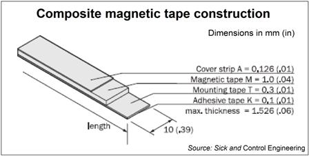
The tape, with its repeating magnetic pattern prerecorded, comes in 90 m rolls. Users determine the encoder’s range by cutting the tape to length for the application. A metal backing stabilizes the iron oxide mechanically, and the pressure-sensitive adhesive layer holds it in place. An overcoating passivates the oxide layer against environmental degradation. The system has been used in elevators and lifts, measuring tables, and automated cutting tools.
Challenge of linear motors
Linear motors present a particularly challenging application for encoders. The linear motor’s advantage is that no gearing or lead screw is needed to convert the motor’s rotary motion to linear motion, so it can move very much faster than a servomotor-based linear motion system. To get accurate position information, the linear encoder has to sense and report position equally as quickly.
In addition, linear motors lack the compact outer frames characterizing servomotor construction. Their stators are exposed to the factory environment. Lack of an armored shell for the motor exposes the linear encoder to environmental insults as well. This requires ruggedness and environmental protection for the encoder.
Mark Eustache, manager of business development with German automation equipment manufacturer Sick, points out that their TTK70 linear encoder was designed specifically for position feedback for high-speed linear motors. “It was mainly a matter of upping the encoder’s readout speed,” he says.
The TTK70 linear measuring system consists of an absolute reading head and a magnetic tape, as measuring scale, 10 mm wide and up to 4,000 mm long. The sensor PCB, which is aligned with the measuring plane, is equipped with Hall sensors on two parallel tracks.
In operation, the absolute position values are calculated by the reading head first detecting the absolute starting position during start-up of the linear motor via Manchester coding. All further positions of the drive are determined via the incremental position on the magnetic track, that is, sine/cosine signals. The values thus formed are transmitted via the company’s Hiperface interface to the evaluation electronics of the linear drive, allowing interpolated position readings with a resolution less than 10 microns at displacement speeds up to 1.3 m/s. At diminished accuracy, it is possible to achieve up to 10 m/s speed.
Inductive linear technology
In a second technology — the inductive linear encoder — the moving element is a transmitter coil operating at a low radio frequency of a few hundred kilohertz. This signal is picked up by coils embedded in a track. The system can determine the moving element’s absolute position relative to the track by determining which inductive loop receives the strongest signal. The system can interpolate between inductive loops by comparing signal strengths from adjacent loops.
Cwach describes the physical appearance of Turck’s inductive linear position sensor, which is available to span distances from 100 mm to 1 m, as a long aluminum extrusion with a 25 mm x 25 mm cross section, and a polycarbonate insert on top. The sensor element sets up a high frequency ac field at 187 kHz. Receiver coils printed on a circuit board in the track repeats every 10 mm. The standard system provides a 12-bit analog output, providing 4,096 pulses within the unit’s measuring range. Enhanced versions provide up to 20-bit, or 1 micron, resolution.
According to Cwach, the unit’s applications include mobile equipment, machining, warehousing, fork lifts, packaging, roller mills, printing machinery, and web processing. The rugged construction achieves an IP64 rating for use in welding, and in applications that involve splashing fluid, such as the food and beverage industry.
The features that characterize applications for these magnetically driven linear encoders include relatively large measurement spans (from a meter to many tens of meters), precise measurements on the order of tens of microns or better, and harsh environments. Magnetic systems are able to meet these needs at relatively low cost because electromagnetic interactions can take place over long ranges, and are relatively immune to environmental interference to begin with. There are also good non-magnetic structural materials, such as aluminum and plastics, which can be used to armor linear encoders against environmental hazards, as well. Magnetic interactions’ long range allows making measurements across millimeter-size gaps with no loss of precision.
– C.G. Masi is a contributing editor for Control Engineering. Reach him at [email protected].
– Also see
CNC machines push linear encoder limits;
Control Engineering sensors new product area; and
Control Engineering motors and drives new product area.
www.sickusa.com