A permanent magnet (PM) motor requires a variable frequency drive (VFD) to operate effectively. See motor comparison table, induction motor vs. PM torque curve, and VFD programming and tuning advice.
Learning Objectives
- Consider induction motors versus permanent-magnet motors.
- Examine VFD selection, programming, tuning for PM motor applications.
- Learn how to verify PM motor operation after VFD setup and auto tuning.
Induction motor (IM) and permanent magnet (PM) motor designs differ, including their use of variable frequency drives (VFDs). IM motors are designed to be able to run using across the line power to run at a constant speed. A PM motor is not designed to run across the line. A PM motor requires a VFD to provide the correct output to effectively operate the PM motor.
Induction motors versus permanent-magnet motors
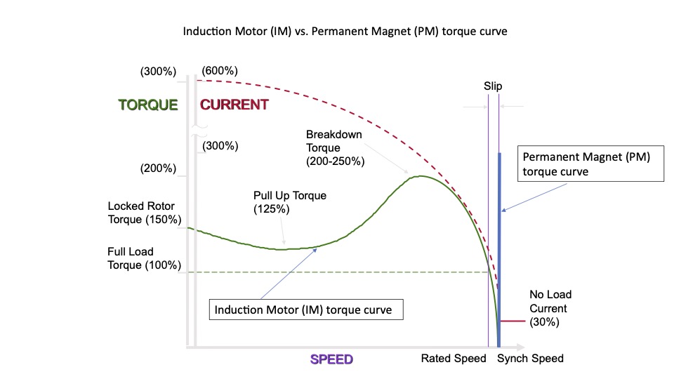
It’s important to understand design differences between an IM and PM motor to control each appropriately with a VFD and to select the most appropriate motor and drive for the application. See Figure, table 1 and Figure 2 showing torque curves for an IM versus PM motor.


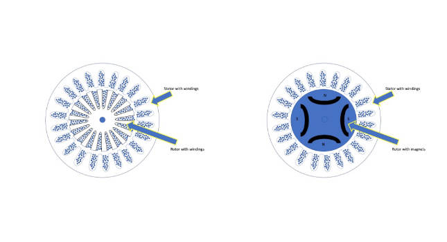
- An IM is an asynchronous motor where slip is required to produce torque. Motor speed is the difference between the command frequency and the slip frequency. Motor torque varies by the slip frequency (in green).
- A PM motor is a synchronous motor where the motor speed equals the frequency commanded by a VFD and torque can only be generated at the synchronized speed (in blue).
An IM and PM motor differ in size. A PM motor design is more compact and efficient than the IM motor because the rotor contains magnets. Because a PM motor already has created a magnetic field, an instant and constant torque is available. The IM rotor is wound and requires the induction from the stator field to create the rotor magnetic field.
PM motors are more complex and require a programmed VFD to operate them.
PM motor data, electro-motive force
A key component to the PM motor is knowing the Back EMF (electro-motive force). A PM motor will naturally generate a voltage by rotating the motor much like a generator. The back EMF voltage is in units of volts per 1000 revolutions per minute (V/krpm). This value is often available on the motor name plate when setting up and tuning a VFD (Figure 3).

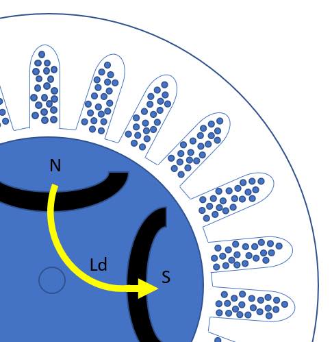
Other key components are the PM motor’s stator resistance and Ld and Lq inductance values (showing the inductance paths). Ld and Lq inductances are the two vector control coordinates that are typically 90 degrees apart. The current that flows through Ld determines the magnetic field’s control. The current that flows through Lq determines the torque production (Figure 4).

Example of PM motor VFD setup, tuning
An example follows of VFD setup and tuning to run a PM motor in a blower-fan application. Prior to setting up and tuning the drive, 10 pieces of information are needed as shown in Table 2.

These are motor model number, motor-rated power (hp), motor-rated voltage (Vac), motor rated frequency (Hz), motor-rated amps (A), motor number of poles, motor stator resistance (Ω), Ld inductance (mH), Lq inductance (mH) and back EMF (V/krpm). If this data is unavailable on the motor name plate, contact the motor manufacturer.
VFD selection, programming, tuning for PM motor applications
The VFD selected must be able to provide proper current and voltage for the selected motor.
As we can see from the motor name plate, the voltage could be 230 Vac or 460 Vac, and the currents also are listed for each. For this example, use the 230 Vac with current of 6.7 A. This VFD model selected here from the chart is appropriate.
When programming the VFD, begin by selecting the control method. This will set up the drive for the parameters that will need to be entered with the values from the name plate and form (Table 2). Figure 6 (first VFD screen) shows a PM motor in the open-loop vector mode selected. The application is a blower fan and doesn’t require feedback such as an encoder for the motor speed feedback to the VFD. Thus, it’s open-loop mode.

Figure 6 (next screens) proceed to the tuning section to enter the remaining data collected from the motor.

There are different auto-tuning methods. The tuning process allows the VFD to calculate and optimize values to more closely match motor characteristics. Information on the data sheet is known, so it isn’t so much a tuning as it is entering motor information.
Certain information may not be easily available in some cases. If so, it can be calculated by the VFD by knowing at least a minimum. In the case of the stationary methods, the drive can calculate the Ld, Lq and R (resistance) or R only. But in either case the back EMF is required. These stationary auto tunes do not rotate the motor. These are preferred in the event a motor is already attached to the application and may not be easily removed. Rotational auto tune methods require the motor to rotate freely or to be uncoupled from the application.
If the back EMF is not known, then a rotational auto tune must be done. This will rotate the motor. In rotational auto tuning, any load must be disconnected from the motor shaft to ensure the calculation is for the motor only. Additional loading will skew the calculations.
The VFD also needs to align the position of the rotor every time it is started. This also is done during the initial auto tune. The VFD can inject a current or a high frequency into the motor’s stator to find the rotor’s magnetic pole. When using a closed-loop system, the encoder feedback device is used as a point of reference.
In this example (Figure 7), using the pull-in method, a dc current is injected to the stator. This creates an attraction to the nearest pole.
After VFD setup and auto tune, verify PM motor operation
Upon setup completion and a successful auto tune, test the motor alone and attached to the application for performance and direction.
If the motor direction is incorrect, motor leads may be miswired. To remedy that, power off and swap any two of the three motor leads (Figure 8).

It also could be the poles of the motor were closer to the magnet in the opposite direction than the forward. This is normal. If continuous oscillation occurs, or an eventual motor step-out fault appears on the drive, additional Ld and Lq parameters may need to be adjusted for finer tuning. Using the high-frequency method may be better if reverse is not allowed for the application.
PM motors are more complex than the IM and may take a little more time to set up and tune. Doing so may also require contacting the VFD manufacturer for further assistance and more appropriate parameter settings.
Robert Bonczar is product training engineer, Yaskawa America Inc. Edited by Mark T. Hoske, content manager, Control Engineering, CFE Media, [email protected].
KEYWORDS: Variable frequency drives, VFDs, PM motors
CONSIDER THIS
Know how to setup and tune a VFD for a PM motor.