Integrate Ethernet-based machine vision and image-based ID readers into factory networks for more direct communications and less expense. See photos, examples.

The traditional approach to integrating machine vision systems or image-based ID (identification) readers with factory automation involves connecting to a personal computer (PC) with a dedicated serial line or USB port and running a translator program on the PC to interface to the programmable logic controller (PLC) running the line. The latest generation of machine vision systems and ID readers offer substantial improvements by providing Ethernet connectivity and tools to communicate directly with PLCs, robot controllers, PCs, and human machine interfaces (HMIs).
Key benefits include eliminating the need for the PC and cabling from the PC to the vision system or ID reader, eliminating the need for software on the PC, and the ability to communicate with the vision system or ID reader from anywhere on the factory network. Interfacing factory networks with vision systems and ID readers has become easier with new communications interfaces, as examples show.
Device-level interfaces
Traditional methods of interfacing between factory networks and ID readers and machine vision systems use RS232 serial lines or USB connections to a personal computer. The personal computer runs translation software or a custom script that parses the data and pushes it to a PLC and sometimes to other network destinations. This approach involves expenses such as purchasing and programming the PC and providing cabling to the ID reader or vision system. In the past, manufacturers would often multiplex vision systems from one PC to distribute vision at multiple points on the production line.
Traditional methods can involve considerable expense in purchasing the PCs and cabling used to connect vision systems and ID readers. Even greater expenses may be involved in developing or purchasing and configuring the translation software running on the PC. The number of code readers or vision systems that can be connected to one PC is limited, so this approach is not easily scalable. Companies required to maintain good manufacturing practices (GMP) incur additional expenses for validation of the PC and software. Another limitation of the traditional approach is that the ID reader or vision system communicates only with the PC to which it is directly connected. Thus, it can be challenging to interface with other applications, such as statistical process control (SPC), or to download configurations to multiple vision systems, such as during model changeover.
Ethernet interfaces, control level
The latest generation of ID code readers and machine vision systems incorporate Ethernet ports that enable them to be directly connected to any switch or hub on a factory network and in turn communicate with all other devices on the network. The latest vision systems and ID readers also include tools that make it easy to interface directly to common factory automation hardware, such as PLCs, robot controllers, HMIs, and PCs. This approach eliminates the need for the PC and cabling from the PC to the ID reader or machine system, providing significant cost savings.
Additional cost savings arise from the elimination of software on the PC and, for industries subject to GMP, the elimination of the need to validate the PC and its software. Direct Ethernet communications between the ID reader or machine vision system and the factory network improve scalability by making it possible to add ID readers or vision systems without having to add other hardware or software. The newer vision systems and ID readers also generally include RS-232 and USB connectivity, which enables direct connection to a PC for setup and troubleshooting as well as implementation in legacy applications.
Because they can be easily linked together and managed as a system over a network, the overall cost and effort involved in implementing and maintaining vision is reduced. Networked vision systems, vision sensors, and ID readers enable data and images from all devices to be collected at a central point, viewed on a single monitor, and archived for trend analysis and continuous process improvement. Networking also allows vision systems to increase manufacturing agility by automating procedures, such as changeovers for mixed-model processing.
Advanced vision systems and sensors offer software tools to centralize application development and network administration. An engineer can set up and modify vision applications, share applications with other plant sites, and remotely troubleshoot problems with technicians, all without ever leaving the office. Such tools make it very easy to add new vision sensors to an existing line or copy existing vision sensor applications to new vision sensors for reuse on a new line.
Integrating vision, factory networks
To achieve these benefits, the ID reader or machine vision system must communicate with other factory automation devices such as PLCs over the network. A number of industrial Ethernet protocols are most commonly used for this purpose:
– EtherNet/IP—This ODVA protocol enables vision systems to be linked to compliant PLCs and other devices over one Ethernet cable, eliminating the need for complex wiring schemes and costly network gateways. www.odva.org
– Modbus/TCP—This industrial network protocol (Modbus Organization) permits direct connectivity to Modicon PLCs and other devices over Ethernet. www.modbus.org
– Profinet—This industrial communications protocol is defined by Profibus International and allows vision systems to communicate with compliant PLCs and other factory automation devices. www.us.profinet.com
Typical communications capabilities include preconfigured drivers, ready-to-use templates, and sample code to accelerate system setup and ensure smooth communication with factory automation robots and controllers. An array of visualization options are typically provided for integrating inspection images into a central operator interface. A point-and-click configuration interface is used to control multiple vision systems from a network PC and allows users to easily transfer data and images to an enterprise file server or display them in the user’s own operator interface.
New vision systems provide drivers, templates, and sample code for open standard industrial Ethernet communications protocols such as MC Protocol, EtherNet/IP, and Profinet for connection to a wide range of PLCs and other automation devices from Mitsubishi, Rockwell, Siemens, and other manufacturers. Vision systems can communicate with almost any make or model of robot. Preconfigured drivers, ready-to-use templates, and sample code are available for robots by ABB, Denso, Fanuc, Kawasaki, Kuka, Motoman, and Staubli. Communication with robots by Mitsubishi, Adept, Epson, and many other manufacturers is also supported. Discrete I/O and serial protocols are available to support older PLCs and devices without network connectivity. Fieldbus support is provided for established standards, including CC-Link, DeviceNet, and Profibus.
Visualization options are provided to integrate inspection images, quality data, and interactive controls into an operator interface. One typical approach embeds the vision system image and custom display into a NET or ActiveX compatible custom application, or a PC-based HMI system from Rockwell, Wonderware, Citect, and others. OPC Servers (OPC Foundation) can be used to uplink vision data to HMI displays, SPC systems, plant supervisory systems, and Microsoft Excel to monitor operations and record statistical data. Software development kits can be used to create a custom user interface for managing vision systems.
ID reader/PLC connectivity example
The example shows how a vision system or ID reader can be connected via EtherNet/IP using a Rockwell Add-on profile (AOP). The first step is to load an electronic data sheet (EDS) file supplied with the vision system into Rockwell’s EDS wizard software, RSLogix. EDS files are simple text files used by network configuration tools to help identify products and commission them on a network. The vision system or ID reader AOP is then loaded using Rockwell’s AOP setup utility. The third step is to set up a new module on the PLC, add a unique name, and set the IP address of the reader. The final step is defining the input and output nodes. Then the engineer can write the application and define the associated logic in the familiar Rockwell Automation programming environment.
Odyssey Machine
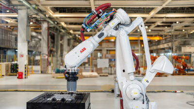
Before a foundry can deliver 40-lb aluminum clutch housings to its customer, it must saw off the sprues and remove flash. Previously, one operator loaded the castings into a machine that sawed the sprue off and a second operator held the castings while another cutter removed flash. Odyssey Machine Company of Bowling Green, Ohio, developed a vision-guided robot application that eliminates these difficult and potentially dangerous tasks. A machine vision system identifies which of eight parts is on the infeed conveyor and the location of that part. The robot then picks up the part and loads it into the three-stage sprue saw. Next, the robot takes the part from the saw and moves it around a high-speed cutter in a secondary fixture to remove flash.
Robot picks clutch housing
The workcell runs under the control of an Allen-Bradley programmable logic controller (PLC) which is connected to the vision system with an Ethernet cable. The robot used in this application is a Fanuc S900W that the customer had previously retired but was rebuilt by Fanuc for this application. The PLC was easily connected to the vision system via an Ethernet connection because it contains protocols needed to communicate with the PLC. The vision system is connected to the RJ2 robot control with digital input/outputs to communicate with the robot controller. The vision system sends the part identification information and the coordinate information on the part to the PLC, which sends information to the robot controller.
Verification, tracking
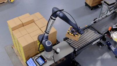
In the state of Texas, a tax stamp must be applied to each liquor bottle sold at the wholesale level, such as to hotels and restaurants. Good-Goody Liquor in Dallas wanted to automate the process of reading the stamps to ensure each bottle has a tax stamp and to store its number in a database with the bottle number for audit purposes. The application presents a major barcode reading challenge. The system processes bottles at the rate of one per second, and the bottles have different shapes and backgrounds. In addition, the label position varies and the lighting changes often.
Cisco-Eagle, the company that built the automated system for applying the stamps, worked with Goody-Goody Liquor to develop a system that automatically applies the tax stamps with 1D barcodes and reads the barcode for verification and tracking. Machine vision is used to identify bottles that do not have a stamp on them so they can be removed from the line. Machine vision is also used to capture the tax stamp number so it can be entered into a database along with the bottle number in case of an audit.
The ID reader communicates using EtherNet/IP protocol and has a driver for PLCs that simplifies the integration task. Once the driver is installed in the PLC, the camera shows up as a component in the PLC. The PLC can then be easily programmed to issue any commands to the camera such as to capture an image with minimal programming. In this application, issuing the command to the barcode reader to capture an image, provide feedback on whether or not a barcode was detected, and send the barcode number was accomplished with three lines of code.
Streamlined communications
The need in the past to use PCs to interface with vision systems and ID readers required the purchase of expensive hardware and development of sometimes complex software to interface with factory networks. A new generation of vision systems and ID readers with built-in Ethernet connectivity and tools for interfacing directly with common factory automation devices streamlines factory network integration. In addition to reducing the time and cost required for implementation, the new devices also increase the value of vision systems and ID readers by enabling the information they generate to be more easily accessed and used in other applications.
– John Lewis is market development manager, Cognex, Natick, Mass. Edited by Mark T. Hoske, content manager CFE Media, Control Engineering, [email protected].