A reimagined production line delivers complete flexibility to accommodate simultaneous programming and testing of a broad range of terminal types.
Learning Objectives
- Understand the capabilities of new mechatronics technologies.
- Explore the machine design possibilities made available by 6D of freedom in motion control.
- Prepare for adaptive manufacturing concepts that will enable mass customization, high-mix low-volume production and other capabilities.
Mechatronics insights
- Beckhoff’s automation system dramatically increases testing capacity, showcasing the power of adaptive technology integration and process optimization.
- Using a planar contactless motion system and precision positioning, the system’s modular layout ensures adaptable and efficient operations, enabling future expansions without major overhauls.
- With thorough electrical and optical testing, including calibration and color intensity checks, the system ensures high-quality output and customer satisfaction.
Developing automation, input/output (I/O) systems and mechatronics to help companies rethink what’s possible isn’t enough. Leading by example with an adaptive automation in-house application can help.
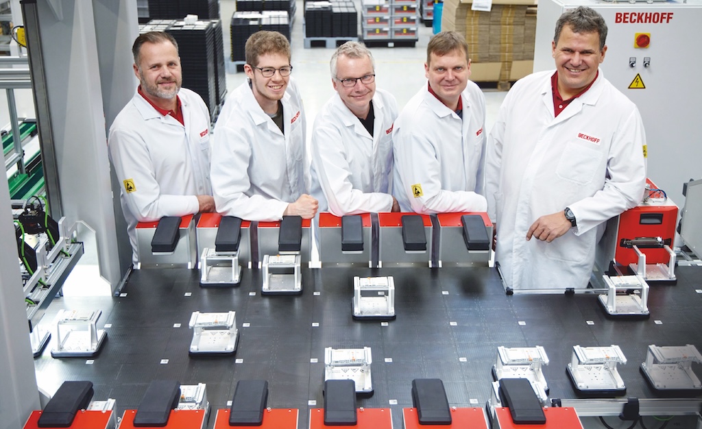
Keeping pace with manufacturing growth is a constant challenge for Michael Golz, head of the demo systems department at Beckhoff global headquarters in Verl, Germany. So it’s important not to get stuck in the status quo for Golz and his team of approximately 40 employees, who build manufacturing equipment, among other tasks.
Goal: Exponential increase in manufacturing testing capacity
In fall 2021, Golz’s team and product management experts reimagined how to perform final inspections of input/output (I/O) components. The goal was to exponentially increase testing capacity in a high-mix low-volume (HMLV) process.
The resulting I/O manufacturing system can program, adjust and test 1,200 terminals per hour (about 10,000 per shift) automatically. This concept depends on PC-based control and many EtherCAT solutions, working in concert with specially developed firmware and test stations. This mix of technologies delivers high speed and throughput as well as flexibility for today and tomorrow.
“On average, a fully tested I/O terminal that is programmed with the appropriate firmware leaves the system every 3 seconds, regardless of the type of terminal and the order in which they are delivered,” Golz said.
Currently, the system can program and test roughly 80% of many terminal types. The product mix present in the system at any time has zero impact on the line’s throughput… that’s huge, he suggested. Considering the variety of terminals — with or without field programmable gate arrays (FPGA), a controller, or with analog channels — the programming and subsequent function testing of each terminal require different amounts of time.
“It can take up to 30 seconds for the firmware to be installed and all analog channels to be adjusted,” said Stefan Engelke, whose team developed the universal test cabinets.
However, the complete freedom in motion available delivered the necessary flexibility for the entire internal logistics and infeed of the terminals to the workstations. As a result, it no longer matters whether a bus terminal needs to spend 10 seconds or 1 minute at a firmware programming or testing station. The remaining movers simply move to the next free station rather than idling in a fixed-pitch queue. So individual delays don’t affect the overall output of the system.

Flexible and transparent handling, simplified
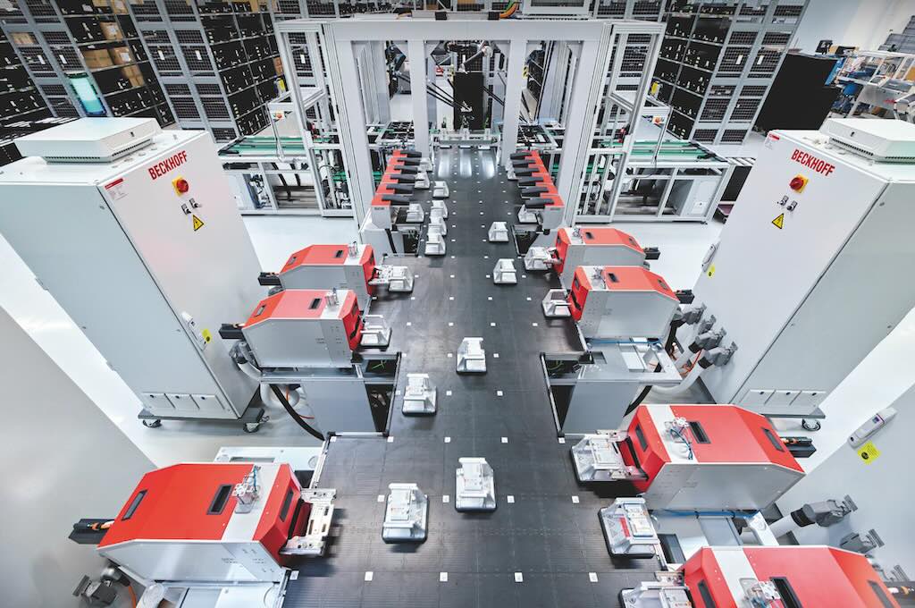
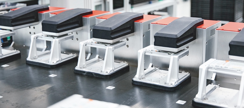
The process begins when trays carrying I/O terminals move from the infeed station into the picking station. A delta robot picks up the terminals and places them on waiting movers. The system has two main paths, almost like highways, leading left and right to the programming and testing stations. The stations are located at “parking spaces” along both lanes. Between the lanes, movers return to the picker on a third path. With this symmetrical setup, one side of the system can continue to operate even if the other goes down.
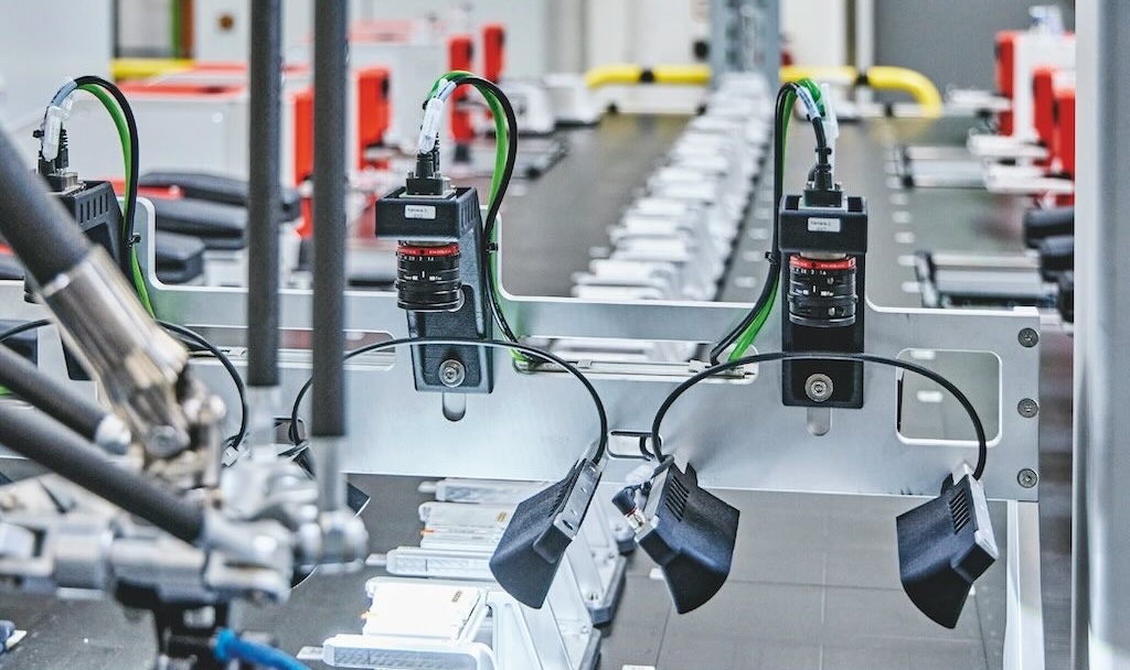
The movers pass the terminals under a reading station through to the lateral programming stations. The reading station captures the individual Beckhoff Identification Code (BIC) of each terminal via multiple company vision hardware and software technologies.
“After that, the system knows the terminal type and does everything completely autonomously – programming, adjusting the analog channels if necessary and function testing,” said Ulrich Brockhaus, who is responsible for system programming.
At the same time, the BIC is “married” to the mover via its ID. The mover ID also can be used to track the location of each individual mover or terminal, even after a power failure. When the mover reaches a free programming station, it positions the terminal precisely under its contact pins. Then, the corresponding firmware is loaded onto the terminal based on its BIC.
It then moves to a universal testing station, which in turn calls up the device-specific test sequence based on the BIC. If the software has been loaded correctly and the function test reports no issues, the mover transports the terminal to the picking station’s second delta robot, which places the terminal on another tray, via the middle track. The mover passes through the reading station a second time, only this time in the opposite direction.
“The terminal is booked out via the renewed capture of the BIC on the return track,” Engelke said. “The installation of the firmware and the function test of each individual terminal are documented in the central database, including all adjustment values in the case of analog terminals.”
All degrees of freedom used in tile-based motion control
A system consisting of 100 tiles forms the base of this fast, flexible process. The two main paths with two outbound lanes and the return track in the middle from six base sets of planar tiles with contactless movers, each containing 3 by 4 tiles, Golz said.
For the add-ons (programmer and tester), the remaining 28 tiles are screwed onto the side of the basic system. Each mounting position has a standardized interface with power supply (400 Vac), safety, Ethernet local area network (LAN), as well as EtherCAT.
“The interface and the system layout enable future expansions without major conversion work,” said Daniel Golz, who is responsible for the mechanical design of the system and the specific details for terminal contacting.
The floating planar motion control system enables highly modular machines while simplifying mechanics in many sectors. For example, the programming stations use XY precision positioning. As a result, programmers can immediately lower their pins after reaching the exact position onto the terminal contacts and start loading the firmware.
At the test stations, another feature reduces the design work: the variable flight height. When it arrives at the test station, the mover lifts first so that the slide-in unit of the test station can move under the terminal. Then the mover lowers its hovering height again, so the terminal comes to rest on the slide-in unit and is drawn into the tester. As such, all contacts are freely accessible and can be contacted. After the test, the terminal returns to the mover in reverse order.
The option to rotate the movers comes into play again during insertion and removal. Movers can rotate by 180 degrees, depending on the side of the system used.

Four benefits of planar contactless motion system
“This feature has also significantly reduced the mechanical complexity and has made space-saving configuration of the tester and programmer on both sides possible,” Daniel Golz said.
The system layout benefits from four properties:
-
The 2D product movements individualize transport of the terminals and facilitate parallel processing in the programming and testing stations.
-
XY precision positioning means there is no need for a handling system at the programming stations.
-
The transfer of the bus terminals with the aid of the Z movement (lifting/lowering) replaces complex mechanics in the test stations.
-
360-degree rotation enables the mirror-symmetrical set-up of the system.
Electrical and optical functions, PC-based control
The testing stations don’t just check the electrical properties and functions of a terminal.
“For terminals with analog signals, the corresponding test sequences and calibrations are included too,” Engelke said. An integrated vision system checks that the prism is present and in the correct position and measures the colors and intensity of the LEDs in the terminals.
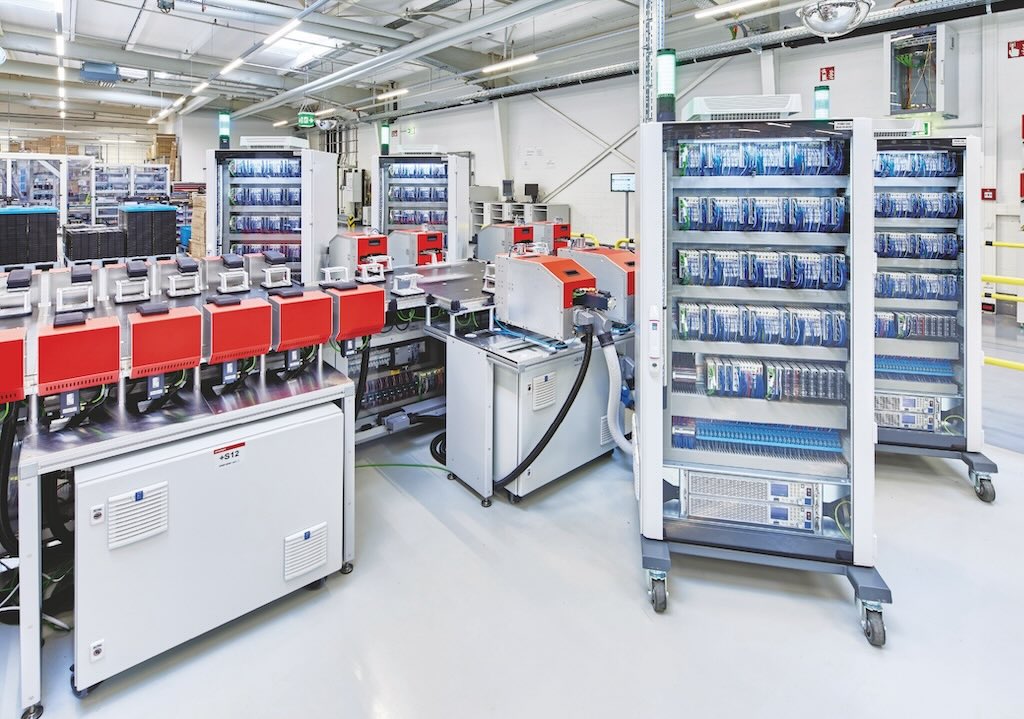
A very wide range of EtherCAT terminals, with diverse functions and measuring ranges, can be tested automatically on the system using the universal test cabinet. Its complete measurement and testing system is focused on precise measurement terminals. Mounted in mobile cabinets and coupled to the system by means of a plug connector, the test cabinets can be replaced quickly, without shutting down the entire system. This needs to be performed regularly, since the terminals are measurement devices which must be recalibrated and certified in specific cycles.
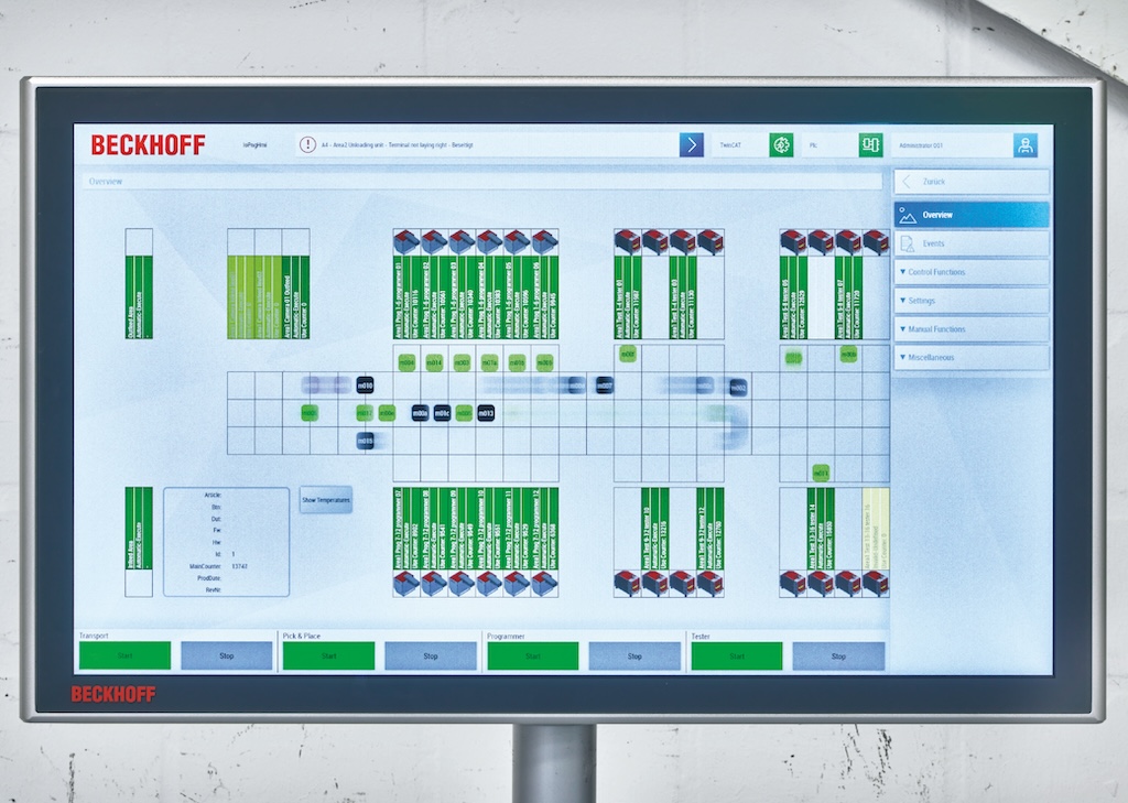
The strengths of PC-based control are evident in the overall coordination and evaluation. If a tester detects a discrepancy on a terminal, this is registered via the BIC while the tester sends the terminal back to the programming stations for reconfiguration. However, if error messages accumulate on a programmer or tester, this indicates a malfunction.
“In this case, the tester is reported to the system as unavailable,” Brockhaus said. “This position is no longer approached by the movers until the tester has been examined and, if necessary, replaced.”
Although the system will operate with one less station, it’s still up and running and not significantly slower. “An I/O terminal that could cause any problems for a customer would not leave our system,” said Michael Golz.
The system is a prime example of how PC-based control can perform a wide variety of tasks and functions. In addition to a control cabinet industrial server, which coordinates the 33 movers on the 100 tiles, a total of 10 ultra-compact Industrial PCs control the other system components.
Drive technology for the delta robots is handled with the multi-axis servo system and servomotors.
The design uses “integrated servo drives to infeed and eject the trays because they are extremely compact and only require EtherCAT and 48 V to operate,” Brockhaus said.
Linear actuators are used by the programmers to contact the terminals, and the testers use electric cylinders to feed in the terminal carriers. All machine safety technology is implemented with a system that integrates safety technology into the EtherCAT I/O system. In addition to many series terminals, around EtherCAT measurement terminals are installed in each of the four test cabinets.
“Our I/O terminal portfolio offers a wealth of functionality, from 2-channel digital input terminals to compact drive technology, with differing levels of complexity,” said Michael Klasmeier, head of I/O production at Beckhoff. “These are produced in annual quantities ranging from a few thousand to hundreds of thousands of units. All of our I/O products are produced locally in East Westphalia. Our objective is to increase production output with our current employee numbers and in the space available, which would be impossible without automated testing.”
Jeff Johnson, mechatronics product manager, Beckhoff Automation LLC. Edited by Chris Vavra, web content manager, CFE Media and Technology, [email protected].
Keywords: mechatronics, motion control
ONLINE
Further information:
CONSIDER THIS
How can mechatronics and motion control help your operations?


