Protect against electrical noise distortions in monitoring and control signals to help ensure reliable collection of wind turbine data, for safe and efficient wind turbine operation. Can cleaner signals and eliminating ground loops help your application? See online extras: photos, diagram, links, videos.

The wind power industry installed more than 1,100 megawatts (MW) of new capacity in the U.S. in first quarter 2011 and entered the second quarter with another 5,600 MW under construction, the American Wind Energy Association (AWEA) reported in April. There are 400+ manufacturing facilities across the country making components for wind turbines, and dedicated wind facilities that manufacture major components such as towers, blades, and assembled nacelles can be found in every region, AWEA reported. With that growth, there’s an ongoing need for reliable collection of wind turbine data to ensure safe and efficient wind turbine operation and greater need for protection against electrical noise distortions in monitoring and control signals.
Data reliability
Power generation with wind turbines involves a unique set of extreme operating conditions. Turbines generally operate without direct supervision, components are mounted at the top of high towers of 100 ft (30 m) or more, and 6 months can go by between regularly scheduled maintenance operations. During that time, rotating components generate vibration and heat that can cause parts to malfunction and fail, and unwanted electromagnetic interference can adversely affect signal integrity.
Like other power generating technologies, wind turbines generate high voltages and currents. Electrical components must therefore be able to withstand high surge voltages and be immune to the electrical noise that can radiate from generators and switch networks.
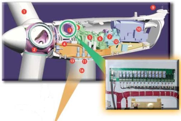
Wind turbine controllers are the heart of wind turbine safety, efficiency, and operability. Controller components usually are located at the bottom of the tower and in the nacelle at the top with a third controller sometimes found in the hub of the rotor. (See wind turbine components diagram.) Controllers can:
- Participate in virtually all safety system decision-making processes
- Oversee normal wind turbine operations
- Monitor hundreds of different functions
- Collect statistical measurements
- Communicate with the wind turbine operator
- Provide internal communications
Sensors in the controllers are used to measure as many as 500 parameters in a modern wind turbine, including generator voltage and current; frequency; shaft rotational speed; wind direction and speed; vibration in nacelle, rotor blades, and bearings; hydraulic pressure; pitch angle of each rotor blade; yaw angle; and component temperatures.
Harsh wind turbine environments (electrical noise, wide temperature variations, transient events, and high vibration) require rugged, reliable signal conditioners for sensor interfaces.
Some isolated analog I/O signal conditioning modules provide ±0.03% to 0.05% accuracy and better than Six Sigma reliability, low output noise, high surge withstand, and a wide operating temperature range of up to -40 C to +85 C. Modules condition and protect critical data acquisition and control signals and connected equipment. Small digital I/O modules can create a rugged, protective isolation barrier between the field and the computer system.
Signal integrity: Isolation, no noise
Electromagnetic interference (EMI) occurs when devices either affect each other unintentionally or are affected by natural causes. While advances in technology stimulate control environment upgrades and retrofits, improve performance, and perhaps even lower costs, new technology can also create new potential for EMI.
Elimination of interference in a system can be difficult because universal solutions to noise problems do not exist. With proliferation of electronics and continually increasing circuit speeds, electromagnetic interference is increasing—making the need for greater and more effective protection of signal integrity essential.
Three basic elements cause noise: (1) a noise source to generate the noise, (2) a receiving device that is affected by the noise, and (3) a coupling channel between the source and the receptor. Signal and power conductors are the simplest means of interconnecting different elements of an electronic system, and these lines are often hundreds or even thousands of feet long. As they go from source to destination the lines often pass through high electric and magnetic fields, which can severely distort the intended signals. Other threats to signal integrity include interference caused by ground loops and differences in ground potentials.
To effectively eliminate or minimize interference problems caused by electric fields, magnetic fields, and ground loops, one of the three elements necessary for a noise problem must be minimized, diverted, or eliminated.
In wind turbines, ground systems carry signal and power return currents, form references for analog and digital circuits, bleed off charge buildup, and protect people and equipment from faults and lightning. Ground loops exist when there are multiple current return paths or multiple connections to “earth ground.”
Current flowing in a ground loop generates a noise voltage in the circuit. The most obvious way to eliminate the loop is to break the connection between the transducer and ground or between the receiver and ground. When this is not possible, isolation of the two circuits is a universal way to break the loop: isolation prevents ground loop currents from flowing and rejects ground voltage differences.
An effective method of isolation uses signal conditioners based on transformers or optical couplers. (See the diagram: Break ground loops with isolation.) The common-mode noise voltage appears across the isolation device internal to the signal conditioner, and noise coupling is reduced to the parasitic capacitance across the isolation barrier.
Signal conditioners also provide signal amplification that reduces signal-to-noise ratios, levels translation, corrects transducer nonlinearity, and provides signal filtering. These features both preserve signal integrity and lessen receiver requirements. As signal conditioners are often rated to withstand transient events, they offer a level of protection for the host system against harsh industrial environments and costly damage in fault situations.
John Lehman is engineering manager, Dataforth Corporation.
More wind statistics
AWEA said in April 2011 that two-thirds of the U.S. capacity under construction is already locked in under long-term power purchase agreements with electric utilities. Over the past four years, the U.S. wind industry has added more than 35% of all new generating capacity, more than nuclear and coal combined and second only to natural gas. The total U.S. utility-scale wind power capacity now stands at 41,400 MW—representing more than 20% of the world’s installed wind power and producing enough clean energy to supply 10 million American homes.
Signal conditioners help wind power, other machine control applications
More than 1000 Dataforth Instrument Class isolated analog I/O signal conditioning modules provide ±0.03% to 0.05% accuracy and better than Six Sigma reliability, low output noise, high surge withstand, and a wide operating temperature range of up to -40 C to 85 C. Modules condition and protect critical data acquisition and control signals as well as sensitive connected equipment. Certain Dataforth analog signal conditioner families suit wind turbine environments. Miniature digital I/O modules are available to create a rugged, protective isolation barrier, effective to 4 kV, between the field and the computer system.
The Dataforth SCM7B34 linearized two- or three-wire RTD input module has characteristics that make it ideal for temperature measurements in many wind turbine components. The block diagram of the SCM7B34 shows how the modules incorporate a five-pole filtering approach to maximize time and frequency response by taking advantage of Thomson (Bessel) and Butterworth characteristics.
The RTD input signal is chopped by a proprietary chopper circuit, transferred across the transformer isolation barrier—suppressing transmission of common mode spikes and surges—then reconstructed and filtered for process control system output.
Like the SCM7B family, Dataforth’s isolated analog SCM5B, SensorLex 8B, and DSCA DIN rail-mount signal conditioning modules are designed for the rugged environments found in the power generation industry. They provide the isolation essential for protecting signal integrity from the interference and noise caused by electric fields, magnetic fields, and ground loops: 1500Vrms transformer isolation, up to 240 V rms field-side protection, and ANSI/IEEE C37.90.1 transient protection. Electrical ruggedness is exemplified by compliance of all products to the ESD, susceptibility, and emissions requirements of CE standards EN61000-6-2 and EN61000-6-4. These modules also conform to stringent industrial requirements for random vibration, shock, and sinusoidal vibration in both operating and non-operating conditions.
In addition, the SCM5B, SCM7B, and 8B modules are fully encapsulated, enhancing their corrosion resistance, with a wide operating temperature range of -40 C to 85 C. They also provide secondary protection against lightning strikes and other overvoltage events.
Dataforth signal conditioner families meet the rigorous standards required for data reliability and signal integrity in wind-turbine and other rugged machine-control applications.
Related reading
Direct-drive Wind Turbines Flex Muscles
Video plant tour: The heart of a wind turbine – link to other wind power videos


