Back to Basics: The term “block diagram” refers to a type of diagram used by engineers to visualize system interactions at a high level. Block-diagram visualization allows system engineers to separate needs analysis from system design, and start system-level design before finishing component-level designs.
The term “block diagram” refers to a type of diagram used by engineers to visualize system interactions at a high level. Block-diagram visualization allows system engineers to separate needs analysis from system design, and start system-level design before finishing component-level designs.
Many authors have attempted to lay down formal rules for building block diagrams. In general, however, these rules tend to have limited applicability. As Captain Jack Sparrow’s crew likes to say: “We think of them more as guidelines than as actual rules.”
Some useful guidelines include:
-
Represent subsystems by rectangle shapes.
-
Interconnect blocks with unidirectional directed (arrow) lines.
-
Identify each block with a subsystem name.
-
Write transfer function formulas for each output into the each block.
-
Label all inputs and outputs with an appropriate variable designation (such as Vi for input voltage and Vo for output voltage).
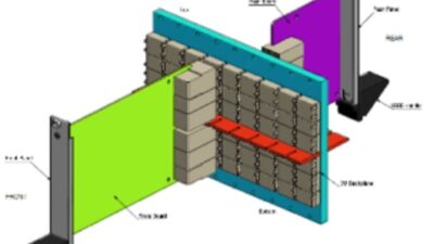
| Block diagrams styles are almost infinitely variable. |
Valid block diagram styles vary enormously. Sometimes block diagrams in Control Engineering use two dimensional rectangular shapes, sometimes they use three dimensional boxes, and sometimes they use graphical representations. What is always important is that the visual representation portrays the important relationships in a concise and easily understandable way.
Function block programming
Because block diagrams are a visual language for describing actions in a complex system, it is possible to formalize them into a specialized programmable logic controller (PLC) programming language. Function block diagrams are one of five programming languages defined in part 3 of the IEC 61131 standard. Since this is a real, bona fide computer programming language, it is highly formalized with strict rules for how diagrams are to be built.
Directed lines are used to connect input variables to function inputs, function outputs to output variables, and function outputs to inputs of other functions.
It is important to keep in mind that these blocks portray mathematical or logical operations that occur in time sequence. They do not represent the physical entities, such as processors or relays, that perform those operations.
The rules require logical sequence to go from left to right and top to bottom. This rule expresses the fact that the function block diagram is a computer language depicting actions that happen in time sequence.
Software packages are available to make building specialized block diagrams for most engineering disciplines. Microsoft’s Visio Technical includes templates for general purpose, as well as special purpose, block diagrams. Of course, engineers have been scratching out block diagrams by hand on paper, chalkboard, and backs of envelopes for centuries, and this method is often the quickest and easiest way to organize your thoughts.
| Author Information |
| C.G. Masi is a senior editor at Control Engineering. Contact him at [email protected] . |


