Global navigation satellite system (GNSS) and real-time kinematic (RTK) measurements can be used to help with crane monitoring in real time, calculating position, velocity of points, and baseline attitude information at the same time. Products can be customized based on monitoring functions required.
Portal cranes are mobile, and crane operation is most important. Crane accidents [1, 2] can cause huge economic losses and even casualties. Monitoring real-time portal crane operations is helpful to resolve increasingly prominent safety management issues. The prior programmable logic controller (PLC)-based control system for the portal crane provided only data for amplitude and load, not its attitude, speed, and other information. The system has large measurement error, scattered information, is difficult to integrate, and monitoring system accuracy is not high.
Research focused on testing and analysis of monitoring 3D altitude in real time using global navigation satellite system (GNSS) and real-time kinematic (RTK) measurements. Results follow looking at GNSS and RTK for altitude measurement, using a server for real-time monitoring, accurate control, and refined safety management of a portal crane.
Portal crane application
The portal crane widely serves as the main hoisting equipment for loading and unloading, because of its good performance, and it is increasing in use with the rapid development of world shipping. With increased use, collisions of portal cranes, buildings, and surroundings are more frequent. More careful monitoring of crane luffing (moving the hook in and out from the base at the same level), running position, and lifting height can effectively prevent accidents.
A large portal crane uses rotating amplitude monitoring technology, installed on an angle sensor or in the joint of the jib and at the base of its tower [3]. The installation of angle deflection measurement method based on mechanical principles is complex and needs high precision, and is also significantly affected by mechanical wear and aging. Another way is to use the encoder that indirectly measures angle by measuring the speed and distance of the portal crane [4]. Accumulated error exists in this method, and it relies on magnets to reset, at a cost.
The research calculates and transforms coordinates of the attitude data of baseline between each point on each jib of the portal crane in real time, and then calculates the position, posture deformation, rotating amplitude, the swing arm elevation, etc. The tested portal crane is at Guangzhou Wenchong Shipyard Co. Ltd. Data shows that the real-time monitoring scheme using GNSS-RTK technology for portal crane slewing luffing attitude is feasible. The hardware used includes GNSS receiver, GNSS antenna, and RTK multi-baseline attitude calculation server. When in use, the system is independent of the portal crane moving parts and prior control system. Advantages include easy installation, long service life, real-time and continuous attitude monitoring data, no accumulated error, no influence from the portal crane running speed and position, and high measuring accuracy.
Portal crane attitude real-time monitoring
Portal cranes are widely used, but not widely monitored.
At present a great majority of portal cranes only measure the luffing and load, and they still use the shift control. Sensors were installed in the portal crane to acquire and display the attitude and velocity data and improve safety and operational efficiency.
The portal cranes’ density in shipyard dock is very high. Workers and drivers prevent accidents with visual cues, but the field of view is limited, and the environment can add risk. An automated collision avoidance system is needed.
Domestic shipyard production management is relatively extensive, mainly using Microsoft Excel, Project, and other common software for planning management. Task distribution and feedback are mainly finished through oral communication and filling in manual forms. Careful management of lifting tasks is required for lean management and control. The solution consists mainly of three parts:
1) The portal crane attitude measuring sensor.
2) Data acquisition display and control server for data acquisition, processing, display, storage, and transmission. Through information in the server, real-time portal crane operations data is available with scheduling and alarms.
3) The portal crane information management system for production planning, task allocation, and maintenance information, which is technically feasible, but this project focused on the first two parts, the attitude measuring sensor, algorithm design, and usability of the data acquisition display and control server as research keys.
Proposal with attitude
The proposal for real-time monitoring of portal crane attitude focuses on the multi-baseline deployment of multiple GNSS antennae and calculation of attitude data by the RTK multi-baseline attitude calculation server to get the crane’s attitude.
The attitude measuring sensor consists of a GNSS antenna and GNSS receiver. The GNSS receiver has a dual band of 10 Hz and supports the satellite signal channel of GPS, GLONASS (Russian acronym for global navigation satellite system), and satellite-based augmentation system (SBAS). The GNSS receiver is integrated with the Wi-Fi module. The antenna and receiver are separated by less than 0.5 meters when installed. The data from the receiver is finally transmitted to the RTK multi-baseline attitude calculation server by the local area wireless network to get the attitude solution. The RTK multi-baseline attitude calculation server also handles functions of the display, control, and remote transmission of sensed data-that is, the data acquisition display and control server.
GNSS antenna deployment
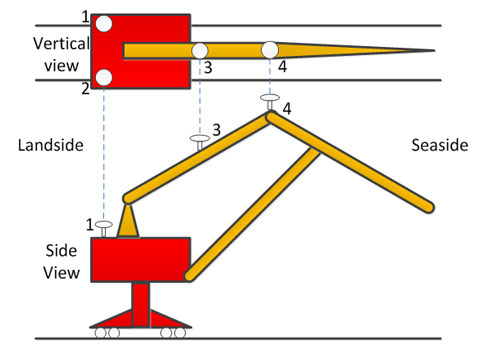
As shown in Figure 2, the driving link handles the jib motion of the portal crane. The connecting shaft enables the link’s dual rotation. With geometric correspondence, a GNSS antenna only is needed on the driving link. The GNSS antenna location should be where satellite signal intensity is unaffected by the rotating jib. Higher signal reception is better. The installation locations of GNSS antennae on the portal crane are shown with 1,2,3,4 in Figure 2.
Baseline combination, reference value measurement scheme
After checking portal crane drawings, we can diagram antenna distributions, as shown in Figure 2. In the figure, the line O represents the rotation axis of portal crane, and the lines AB, AC, CD, and BE separately represent the four-bar jib. The points A’, B’, D’, and E’, respectively, represent the projection on the canopy plane of the points A、B、D、and E. The antenna 1, 2 installed on the canopy is represented with point M, N. The antenna 3, 4 installed on the jib AB is represented with point P, B. In Figure 2, L is used to show the length of a certain line. For example, LMN represents the length of line MN.
In this study, the XYZ orthogonal coordinate system is used where the Z axis is perpendicular to the horizontal plane (parallel to the spindles of the portal crane), and the XY plane is parallel to the horizontal plane. Its coordinate origin and direction of the x, y axis are determined by the earth-fixed coordinate (ENU, East, North, Up coordinates) system or the orbit coordinate system. In Figure 2.2, (x,y,z) represents the coordinates of each point. For example, the coordinates of point P are P (x,y,z), its horizontal coordinate is P (x, y), and the three components of the coordinates are Px, Py, Pz separately.
After the zero setting of the portal crane’s large cart parts and so on, the jib rotates back until it points seaside where its rotating amplitude is smallest. Then the following reference values will be calculated:
(1) Length, direction angle, and pitch angle of baseline LMN, LPB, and LBE in the mode of mobile base station.
(2) East, North, Up coordinates of antenna M, N, P, B in the mode of fixed base station.
(3) East, North, Up coordinates of the endpoints in both sides (seaside and landside) of the two tracks and zero point.
(4) Up coordinates of antenna M, N, P, B in each position of track when the large cart parts is running.
Among them, the baseline is a geometric vector from the base station to the rover station. The mode of mobile base station is the calculation mode that the base station is mobile, and the mode of fixed base station is the calculation mode that the base station is fixed.
We can further calculate the attitude solution needed from the above-mentioned reference values. The direction angle is exactly the direction of the jib of the portal crane. The working radius and lifting height of the portal crane can be calculated by the length of each jib arm and their pitch angle. The location in the orbit and each component of the running attitude can be calculated by coordinate change formulas. For the baselines from any couple of antennas in this system, the portal crane turning angle is the difference between the direction angle and initial value. In addition, the rotating amplitude LOE’ can be easily calculated by the known geometrical relationship of the portal crane drawings and each baseline’s length.
The application requires accurate calculation of each reference value, which is to say, the accurate real-time calculation of length of each baseline, direction angle, pitch angle, and East, North, and Up coordinates of the rover station.
Portal crane attitude monitoring
The operating principle of the RTK multi-baseline attitude calculation is resolved in an algorithm in the server. The major difference between the fixed base station and mobile base station calculation arithmetic here is that RTK-PPP (RTK-precise point positioning) needs to get longitude, latitude, and altitude of the rover stations for the initial value of the next step. Two kinds of calculation arithmetic are similar.
Baseline attitude computational algorithm
There is only a baseline vector in the application of the single baseline attitude measurement, which provides its two-dimensional attitude, namely direction angle, pitch angle, and baseline length, for the precise position of the rover station in 3D space. As an example, for the antennas M and N, antenna M is a reference station and antenna N is the rover station. We suppose (XM, YM, ZM) as the geocentric 3D coordinate of antenna M and (XN, YN, ZN) as that of antenna N.
We can get the observation equation according to the phase observation value received by antenna M:
(1)
The parameters in the equation are defined as the following:
N: Carrier phase ambiguity
Φ: Phase fraction
Λ: Wavelength of a carrier
L: Actual distance from antenna to satellite
Τ: Receiver clock error
Σ: The tropospheric and ionospheric delay correction of satellite signals
(Xs, Ys, Zs): Instantaneous earth-center coordinates of satellite.
Two paths of signal from the satellite to two antennas could be considered equal, because the GNSS antennas are all installed in the portal crane more than 20,000 kilometers away from a satellite. That is, the ionospheric and tropospheric delays of signal from the same satellite to two antennas are equal [7, 8]. After subtracting two observations that two antennas get at the same time, the ionospheric and tropospheric delays are eliminated, and orbit biases of the same satellite and satellite clock bias [9] can be eliminated to get the following single difference equation:
In the formula, the subscripted variables are numbers of antenna M and antenna N, and the superscript variable is the number of the satellite. Definitions for each variable are as follows:
: Difference of two carrier phase integer ambiguities of antenna M and antenna N observing the same satellite at the same time
: Difference of two phase fractions of antenna M and N observing the same satellite at the same time
: Difference of two actual distances from antenna M and N to the same satellite at the same time
c(TN-TM): Absolute clock error of two respective GNSS receivers of antenna M and antenna N. GNSS receiver clock is usually 10-6 [10].
The absolute clock error is almost impossible to estimate. By subtracting two single difference equations, namely the above equation (2) of antenna M and antenna N observing two satellites at the same time, we get the double difference observation equation:
In the formula, is the difference of two carrier phase integer ambiguities of antenna M and antenna N between two epochs;
is the difference of two phase fractions of antenna M and antenna N between two epochs;
is the difference of two actual distances from antenna M and N to the same satellite between two epochs.
Then the equation (3) is linearized. By assuming that the approximation of the baseline vector MN is
,
its correction is
, approximation of carrier phase integer ambiguity is , and its correction is δN_MN^jk, we can get the following error equation:
In the formula,
If there are n satellites, antenna M and N observed at time t, we could get n-1 error equations. At the same time, we need n-1 carrier phase integer ambiguities. So there are (n-1)+3 unknown numbers. By observing p epochs with antenna M and N, we can get p(n-1) error equations. Thus we get redundant observations that could be solved with least the squares principle [11]. The error equation can be put into matrix form:
V=AX+W (5)
In this formula,
A is the coefficient matrix. By assuming that each double-differenced measurement value is equal and independent of each other, we can get the equation:
NX + D = 0 (6)
In the formula, N = ATA, D = ATW.
Hence we get the solution X = -N-1D = -)ATA)-1(ATW). And the length of the baseline and three components of the baseline vector are:
The confidence ratio is the main factor to searching for carrier phase integer ambiguity to guarantee the accuracy of the calculation result. The confidence ratio is the specific value of the posterior variance’s second minimum value to its minimum value [12, 13]. The bigger the confidence ratio, the more reliable the results calculated by the system. The critical confidence rate is 3.0 in this study. When the confidence value is greater than 3.0, the results are available. Otherwise, the results need to be recalculated.
Coordinate conversion
For the baseline vector MN (ΔXMN,ΔYMN,ΔZMN)T calculated above, its reference coordinate system is an ECEF (earth-centered, earth-fixed) system. The coordinate system needs to be converted from ECEF to ENU for better describing the motion attitude of baseline vector. For the moving object on the surface of the Earth, its East, North, and Up coordinate components in the ENU system are more meaningful in physics than its X, Y and Z coordinate components in the ECEF system [14,15].
The transformational relationship from the ECEF system to the ENU system is:
(ΔE,ΔN,ΔU)T = S * (ΔX,ΔY,ΔZ)T (11)
Wherein the coordinate transformation matrix S is:
In the formula, ϕM is the latitude of antenna M, and λM is the longitude of antenna M. The length, direction angle, and pitch angle of baseline MN can be further obtained:
As can be seen from the analysis above, the calculation accuracy of the direction angle and pitch angle solution is inversely proportional to the baseline length solution. The longer the baseline, the higher the attitude solver precision is. As for the fixed-length baselines, their attitude accuracy of the solution is determined by the relative positioning accuracy [16]. The RTK multi-baseline attitude calculation server will complete the algorithm above; that is, it will calculate the real-time attitude data of multi baselines in multi portal cranes whose attitudes need to be measured.
Coordinates calculation of shaft center
We can get attitude data of each baseline and 3D coordinates of the rover station in the ENU system by using the calculation process above. And we also can get the coordinates of the shaft center. We record coordinates of a certain antenna in all positions when the portal crane rotates a circle and calculate the coordinates of the shaft center by using three points of it and the fourth point to verify correctness. To ensure the accuracy of the shaft center coordinates, we can calculate the final value by use of each antenna.
Take point P as an example to show the calculation process, as shown in Figure 3. During rotation of the jib, the four coordinates of point P in four places are P1 (x,y,z), P2 (x,y,z), P3 (x,y,z), P4 (x,y,z). Position coordinates of the large cart is the center of circum circle of triangle P1 P2 P3 and its coordinates are:
The accuracy of point O coordinates can be tested by comparing for equivalence the two distance values.
LP1O、between P1、P4 and O. If not accurate, the coordinates of point O will be calculated by using the other four points on the circumference of the circle.
Calculation of rotating amplitude
After completing the coordinates calculation of shaft center and angular value of θ by calculating baseline attitude created between antenna 3 and 4 directly, rotating amplitude LOE’, namely LOE’ = LOC + LCB’+LB’E’, can be calculated. In this equation, LOC is a known value. The calculation formulas of and are shown in equation (18-25):
Usability analysis for real-time portal crane attitude monitoring
To test whether the proposed scheme can accurately monitor the working state of the portal crane in real time, we collect normal operation monitoring data of more than five hours in this research; that is, real-time measurement of the swing arm’s direction angle and the pitch angle of the portal crane in working condition (the angle θ in Figure 2). The baseline vector PB created between antenna 3 and antenna 4 on the driving link (the installation distance of two antennas is 14 meters) continuously records and observes data. Data recording curves are shown in Figures 4 and 5, representing baseline length, direction angle, and pitch angle, respectively, of this baseline calculated by the RTK multi-baseline attitude calculation server.
The operation process of the portal crane is mainly divided into the following stages:
- From the moment installation is complete at 10:39 to 11:15, the portal crane is in a stationary state. Compared with the latter dynamic observation data, the baseline length, pitch angle, and direction angle are most stable in this period.
- From the moment the portal crane begins work at 11:17 to 11:30, it only has swing action with minimum radius (22 meters) at 60 degrees and maximum radius (45 meters) at 30 degrees, and the direction angle remains unchanged at 80 degrees.
- From 11:30 to 12:50, the portal crane rotates with the load in maximum radius. The change trend of direction angle shows that the portal crane rotates horizontally two round-trips at constant speed during this period. Because the swing arm elevation angle is the minimum, the locus of the direction angle may have a slight jitter, which will stay at 0 degrees (360 degrees) finally.
- From 12:50 to 15:19, the direction angle remains the same except from 13:04 to 13:24, when the portal crane stops running. All portal cranes do luffing lifting work, so the baseline length and direction angle are stable.
- From 15:19 to 16:02, the portal crane does variable rotation until it stops working and its swing arm parallels to the orbit; namely, it points to the landside.
It is noted that real-time baseline length fluctuating around the installation distance in a tiny range is enough to show the accuracy of the calculation. As we can see, the baseline length calculated by RTK has a slight jitter between 12:23 to 12:26. When the portal crane rotates under the gantry crane, the number of available satellites decreases. However, due to this calculation method having a function to keep integer ambiguity, normal resolve can restore immediately after being sheltered.
Aiming at the condition that the calculating results jitter and considering that this paper studies a number of multiple-point baseline solutions, we can adopt universal laws, a trigonometric filtering algorithm, to filter untrusted data. If baseline attitude data meet the trigonometric functions in multiple triangles, then the data is reliable Otherwise, we should calculate again.
According to the stability of the calculation results above, the credibility of the baseline attitude calculation in this study protocol is high, whether the baseline is in uniform motion or in variable motion. The accuracy can achieve centimeter-level and data are always stable and available, which lays the foundation of latter calculation.
Method for monitoring crane attitude in real time
This paper presents a method to monitor portal crane attitude in real time, and describes the implementation process and usability testing. The position, velocity of points, and baseline attitude information can be calculated at the same time. We can selectively customize products based on needed monitoring functions. The scheme for the monitoring of the portal crane slewing luffing attitude is based on GNSS-RTK technology, which completely meets the accuracy requirement of the control system. The controller is connected to the portal crane reducer and brake, which can reduce the speed or braking when the angle of tip exceeds the safety value and alarm the drivers by acousto-optics to improve the safety of portal crane operation. Due to the frequency of attitude solution up to 10 Hz, a GNSS antenna can receive satellite signals better. Given the relatively low speed of host-machine operation, this method meets the requirements in accuracy, stability, and rapidity.
– Li Yan-qin and Jiang Jian are from the Beijing Institute of Technology, China; and Chen Wei is from the Institute of Automation, Chinese Academy of Sciences, Beijing, China. Edited by Mark T. Hoske, content manager, CFE Media, Control Engineering, [email protected].
ONLINE extra
This online article, part of the October Control Engineering archives, www.controleng.com/archives October, has additional information, equations, graphics (above), and references (below), along with related links on cranes and motion control.
See other international coverage at www.controleng.com/international.
Key concepts
- Real-time altitude monitoring of portal cranes can be performed using global navigation satellite system (GNSS) and real-time kinematic (RTK) measurements.
- Measurements can be used to help with crane monitoring in real time, calculating position, velocity of points, and baseline attitude information at the same time.
- Products can be customized based on the monitoring functions required.
Consider this
Sensors and real-time monitoring might lower risk in other industries’ motion control applications as well.
ONLINE extra
References
[1] American National Standards Institute. Portal, Tower, and Pillar Cranes [M]. American Society of Mechanical Engineers, 1990.
[2] Anon A. New Thinking in Mobile Crane Design[J]. Cargo Systems, 1998, 5(6): 81.
[3]Shi L W, Xie H, Wang M, et al. The weight and angle of depression detection and control system of a large portal crane[C]. Fourth International Symposium on Precision Mechanical Measurements. International Society for Optics and Photonics, 2008: 71304N-71304N-6.
[4] Rashid M M, Bin Alamgir T. Design and development of controller of a rotary crane system[C]. Computer and Communication Engineering (ICCCE), 2012 International Conference on. IEEE, 2012: 338-343.
[5] Feng S, Ochieng W, Samson J, et al. Integrity monitoring for carrier phase ambiguities[J]. Journal of Navigation, 2012, 65(01): 41-58.
[6] MozoÁlvaro1, Calle J, David1, et al. Demonstrating in-the-field real-time precise positioning [J]. 25th International Technical Meeting of the Satellite Division of the Institute of Navigation 2012, ION GNSS 2012: 3066-3076.
[7] Xuhai Y, Zhenyuan H, Ji G, et al. Method of common-view time transfer with transfer mode based on geostationary satellite[C]. Frequency Control Symposium (FCS), 2012 IEEE International. IEEE, 2012: 1-4.
[8] RIETDORF A, DAUB C, LOEF P. Precise Positioning in Real-Time Using Navigation Satellites and Telecommunication[C]. Proceedings of The 3rd Workshop on Positioning and Communication (WPNC’06). 2006.
[9]Al-Shaery A, Zhang S, Lim S, et al. A Comparative Study of Mathematical Modelling for GPS/GLONASS Real-Time Kinematic (RTK)[C]. ION GNSS. 2012.
[10]Hauschild A, Montenbruck O, Steigenberger P. Short-term analysis of GNSS clocks[J]. GPS solutions, 2013, 17(3): 295-307.
[11] Broshears E. Ultra-wideband Radio Aided Carrier Phase Ambiguity Resolution in Real-Time Kinematic GPS Relative Positioning[D]. Auburn University, 2013.
[12] Tang Weiming, Sun Hongxing, Chen Jiang. Method of Ratio accumulation of GNSS and fast double-differenced ambiguity resolution[J]. Journal of Geodesy and Geodynamics, 2008, 28(5): 68-72.
[13] Odijk D, Verhagen S, Teunissen P J G, et al. LAMBDA-based ambiguity resolution for next-generation GNSS wide area RTK[C]. Proceedings of the 2010 International Technical Meeting of the Institute of Navigation. 2010.
[14]BianHefang, Zhang Shubi, Zhang Qiuzhao, et al. On GNSS positional error transformation between common coordinate systems[J]. Journal of Geodesy and Geodynamics, 2012, 32(4):83-86.
[15]Shao Y L, Faltinsen O M. Use of body-fixed coordinate system in analysis of weakly nonlinear wave-body problems[J]. Applied Ocean Research, 2010, 32(1): 20-33.
[16]Abbas N N, Jun L Y, Fiaz M. Attitude Determination of small satellite using phase and code measurements of Global Navigation Satellite System: Design, simulation and comparison[C]. Electronics, Communications and Photonics Conference (SIECPC), 2013 Saudi International. IEEE, 2013: 1-6.