Many discrete manufacturers ensure quality control over production processes by directly marking parts with machine-readable codes and tracking those parts through their life cycle. This process is known as direct part mark identification (DPMI). Fast, accurate, and reliable DPMI is a challenge because codes can be difficult to read because of low contrast, variations in part surfaces, and part...
Many discrete manufacturers ensure quality control over production processes by directly marking parts with machine-readable codes and tracking those parts through their life cycle. This process is known as direct part mark identification (DPMI).
Fast, accurate, and reliable DPMI is a challenge because codes can be difficult to read because of low-contrast, variations in part surfaces, and partial damage from process and environmental conditions. If a code is unreadable, the part is not processed, production may stop and an automated machine may go down.
Advances in the power of digital signal processors, imaging sensors, and decoding algorithms have made available ID readers that are cost effective and deliver the reading results that achieve the objectives of discrete parts manufacturers. Important factors to consider when implementing DPMI include the following.

1. Code selection
The American National Standards Institute (ANSI) code standard is the most widely supported for DPMI applications involving metal, glass, ceramic, or plastic materials. Because this code is in the public domain, marking and reading-equipment suppliers have invested significant R&D resources to improve the performance of ECC200 supporting equipment. Some readers, though, work only with proprietary codes tied to a single supplier, or to other code symbologies with fewer product offerings.
2. Data encoding
The data matrix code offers a number of advantages for DPMI applications, including small size, high data encoding capacity, and error correction that allows a code to be successfully read even though as much as 60% of the code may be damaged. Data encoding refers to the amount of information stored within the matrix when the data matrix code is generated. There are 24 square formats and 6 rectangular formats available in ECC200 to provide users the flexibility for encoding between 6 and 3,116 digits in one code.
Code size can affect readability and is generally determined by the amount of data to be encoded, module (cell) size, and surface roughness of the area on the part where the code will be applied. When trying to comply with an industry specification, an application specification will define the size needed for compliance. Deciding what information to encode is typically driven by end-user requirements of the traceability project.
Available space on the part must also be considered. Limited space may require the data matrix code be used as a “license plate” to simply identify the part, reducing the amount of data encoded and size of the code. In this case, a centralized database containing manufacturing and historical data about the part is updated as the part is identified during manufacturing and supply chain processes. When space isn’t an issue, users may take advantage of the large data capacity of the code and encode much more information about the part, creating a portable database.
3. Marking processes
The choice of marking process is typically incorporated into the component design; deviations from this design may require engineering change approval. Primary methods used to produce machine-readable symbols for DPMI include dot peening, laser marking, electro-chemical etching, and ink-jet printing. Important factors influencing the marking process decision include part life expectancy, material composition, environmental wear and tear, and production volume. Other considerations include surface texture, the amount of data to be encoded on each part, and the available space and location of the mark on the part.
4. Mark placement
Location of the code on the part can directly impact code readability. The location should be clearly visible throughout the manufacturing process, and it is best to mark on a flat site on the part. Also, choose a prominent location where the mark is easily viewed by the reader. Avoid locations where a surrounding surface relief could potentially affect code illumination by the reader’s illumination source.
Wherever possible, it is best to provide a “clear zone” around the mark where no features, part edges, noise, or other interference touches the code. When the mark must be placed on a cylindrical part, care must be taken in selecting the size of the code. Surface curvature can create distortions to the code and make proper illumination difficult. Mitigating this problem requires a code size that is no larger than 16% of the diameter or 5% of the circumference of the part.
5. Readability
Readability defines how easy or difficult it is for a reader to successfully read a code. DPMI solution providers must demonstrate they can achieve six sigma read rates—a level of quality with only 3.4 defects per million opportunities. A user looking to implement DPMI must understand all factors that affect code readability. A good baseline for this is to understand the design and other issues related to data matrix symbology and readability.
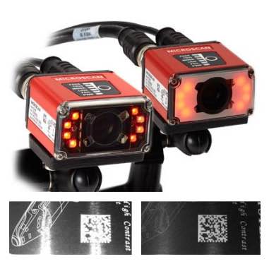
Features that comprise the data matrix symbol are the quiet zone, the finder pattern, the clocking pattern, and the data region. Each individual element is referred to as a module (cell). Actual code appearance depends on the type of mark placed. For example, a data matrix code formed with a laser-marking machine or printer would appear with a continuous L pattern and square modules; dot peen and ink-jet markers produce codes that have a “non-continuous L pattern” with a data pattern made up of round modules.
Robust and reliable code reading requires a pattern with individual modules consistent and distinctly different in shape and size from other features on the part’s surface. However, in DPMI applications this can be challenging due to surface-texture variations, variations in part presentation during the marking process, and inherent variability of the marking machine. For example, bumps on the surface of a cast part will show up in an image. If these bumps are similar in size and/or shape to the dot peen marks of the code, readability suffers because the code blends in with the bumps in the surrounding image.
6. Verification
A verification system can immediately detect a mark-process problem, which could be due to poor part fixturing; damage to the machine, such as a broken tip on a dot peen machine; or incorrect settings during part changeover. Additionally, a code verification system also can provide feedback on the marking process for use in preventive maintenance. For example, the verifier can monitor tip wear on a dot peen machine by monitoring dot size, and flag the operator on the floor when a pin should be changed.
7. Types of readers
Three types of reader (decoder) products are in general use for DPMI today: fixed-mount readers, presentation readers, and hand-held readers.
Fixed-mount readers are used for identifying parts handled and moved automatically by conveyor, indexer, or robot. In operation, this type of reader is mounted in a fixed position where the mark can be placed in front of the reader in continuous or indexed motion. The reader is signaled that the part is ready for reading by a trigger. This trigger event is performed by an external sensor that detects the presence of the part or by an encoder that knows the parts position and can signal the reader to decode.
Similar to a fixed-mount reader, a presentation reader is mounted in a fixed position, but operates in a continuous reading cycle, automatically performing the decoding task once the operator places the part in front of the reader. Presentation readers can provide a fast way of reading part codes in areas where parts are handled manually. A presentation reader can be implemented with a fixed-mount or hand-held reader.
Hand-held readers are preferred in environments where part handling is not automated or parts vary greatly in size. Hand-held readers can be tethered with a cord or cordless. Tethered handheld readers have the advantage of not being displaced from the application location. Cordless operation is required in cases where part size or position is a practical limitation to cord length.
8. Selecting a reader
Consistent code reading is critical; it’s helpful to select readers that can tolerate a wide range of code distortions.
A set of sample parts representative of the range of mark quality should serve as the basis for a preliminary test of a reader’s read rate. However, a more extensive pilot test is recommended so that more read rate statistics can be gathered and analyzed.
The reader also should return a result quickly. Although the main driver for the use of an automatic reader is to eliminate data accuracy errors, readers should not slow down the process or automated equipment.
9. Connectivity
In fixed-mount DPMI applications, read results are usually sent to process equipment or to a database over the factory network, therefore the DPMI reader should offer serial and network communications. Serial communications are used typically in applications where the read or verification results stay “local” to the work cell or factory automation equipment. Network connectivity enables the reader to communicate decoded results data to PCs and databases at the enterprise level.
Finally, as more and more ID readers are used throughout the manufacturing process, it becomes important to have a centralized way of managing them. Ensure the ID Reader allows management and control of vision activity over the network from remote locations in the plant and beyond.
Connectivity methods with hand-held readers depend on whether the reader is tethered (uses a cord) or cordless. Tethered readers often communicate the read result through what is called a “keyboard wedge” interface, which emulates keystrokes, making integration to a PC very simple. Alternatively, communications can be made over an RS-232-C interface. A cordless hand-held reader uses wireless technology, such as Bluetooth, to communicate to the base PC station or other controller.
10. Vendor selection
A vendor should provide the support necessary to thoroughly qualify the DPMI application and ensure the installation is a success. A global network of offices helps with pre- and post-sales support, especially important if the system is commissioned in one location and shipped to another. Finally, the supplier also should have a successful track record and financial stability.
Justin Testa was the senior vice president of ID products for Cognex Corp.
This article originally appeared on April 1, 2005.