Appropriate motor enclosure and motor protective sensors are vital to ensuring safe and long-lasting motor operation. The chosen motor enclosure and protective sensors provide advantages and disadvantages that must be considered based on the intended operation and environment in which the motor will be installed.
Industrial motor protection insights
- Understand the different types of motor enclosures
- Learn about common motor protective sensors and controls
- Determine how to select types of motor enclosures and motor protection devices
Matching industrial electric motor applications with the correct enclosure is important for safe and reliable electric motor use. Electric motors are common at most industrial facilities and are available in a variety of sizes and enclosures for use in several different applications. The application and location influence which motor design and protective sensors are recommended and/or required. Therefore, to ensure safe and long-lasting motor operation, it is important to understand the common enclosure types and general motor protective sensors for different locations and applications.
Enclosure types for motor applications
There are several types of motor enclosures. Some of the common types include:
- Open drip proof (ODP)
- Weather protective (WP)
- Totally enclosed
- Explosion proof (XP)
- Submersible
ODP motor enclosures are an open style enclosure with open vents that allow air to flow directly over the motor windings. This provides excellent motor cooling to ensure the motor does not overheat, and it provides a boost to efficiency. An unfortunate downside to this motor enclosure type is that it allows airborne debris and dust to enter the motor chamber—this can strictly limit the suitable locations for this type of motor enclosure. In general, it would only be acceptable to use an ODP motor enclosure in clean indoor locations.
WP motor enclosures are like ODP motor enclosures with a few additions. These motor enclosures come in two types: weather protective 1 (WP1) and weather protective 2 (WP2). WP1 motor enclosures are essentially ODP motor enclosures with additional screens to prevent the entrance of larger debris particles. This provides a modest upgrade over the ODP motor enclosures and can allow the WP1 motor enclosures to be installed in most relatively clean indoor locations, while still providing substantial motor cooling.
WP2 motor enclosures take the WP1 design to another level by adding ventilation passages with three or more directional changes for the cooling air to travel through. This addition prevents the entrance of most debris and allows these motor enclosures to be installed outdoors as long as the wind speed is not expected to exceed 100 miles per hour (mph), which could drive rain into the motor.
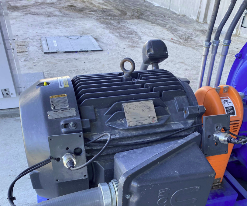
Totally enclosed motor enclosures, as the name implies, are completely enclosed. This prevents the inside and outside air from freely mixing, thereby impeding any ingress of water, dust, and debris. These motor enclosures are available in a variety of types, including totally enclosed fan cooled (TEFC), totally enclosed air over (TEAO), totally enclosed non-ventilated (TENV), totally enclosed force ventilated (TEFV), totally enclosed air to air cooled (TEAAC), and totally enclosed water to air cooled (TEWAC). Figure 1 shows a TEFC motor at a wastewater treatment facility.
Motor cooling for totally enclosed designs
The major difference in all these types is how the motors are cooled. Since the motor is totally enclosed, it will more easily suffer from overheating compared to the more open motor enclosure types that allow direct air flow. For example, motors within TEFC enclosures, operating at lower speeds, common on a variable frequency drive, can have overheating problems because the motor speed is tied to the fan speed. The other totally enclosed enclosures can have additional overheating problems that require design considerations, such as temperature monitoring.
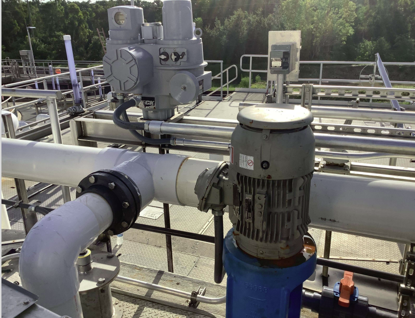
XP motor enclosures are designed for hazardous locations in both inside and outside areas. The enclosure is manufactured with cast iron to withstand an internal explosion without the motor frame bursting or rupturing. The enclosures are built for different hazardous classes and indicate the type of hazardous environment in which it can be placed. These hazardous areas include Class 1, Class 2, and Class 3. Figure 2 shows an XP motor at a wastewater treatment facility.
Submersible motor enclosures, also known as completely enclosed non-ventilated enclosures, are designed to be submerged during operation. These motor enclosures are built with heavy-duty cast-iron frames and use the surrounding liquid for heat dissipation. If not submerged, these motors can overheat within 15 minutes during in-air operation.
These motors are often submerged in hazardous environments and therefore must be designed for the different hazardous classes, much like XP motor enclosures. An additional concern with submersible motor enclosures is the ever-present risk for water to enter the motor. To prevent the ingress of water, these motor enclosures are built with moisture seals and use submersible-rated cable for power and control. However, regardless of the construction, there is always a chance for water to enter the motor, thus requiring a moisture probe to help prolong the motor lifespan.
Motor protective sensors and controls
Motors are typically subjected to electrical and mechanical stresses. Motor control protects the mechanism and operates the motor based on the application. For example, the motor for a pump transferring water from a wet well through a pipe may require an open/close indication from a check valve inside the pipe to ensure that the valve is open while the motor is running. If the check valve is closed, the motor is electrically locked and cannot start until the valve is open. The sensors are in place to turn on/off the motor, as needed, to protect against damage to the motor. However, for all motors, the following motor failure and faults are common, regardless of the application: overloads, overheating, vibration, etc.
- Overloads – Typically caused by either (1) undersizing the motor to perform the work for the application, or (2) a mechanical jamming. Overloads can cause an increased current draw for the motor, thus causing the upstream protective device to trip and/or the motor to overheat and subsequently wearing down the motor windings over time.
- Overheating – Can occur as a result of overloading a motor, insufficient cooling at low speed, locked rotor, etc. Overheating a motor can lead to significant issues such as insulation breakdown and burnt windings, which can damage the motor and potentially cause a fire.
- Vibration – Typically accompanies noise in a motor, which usually indicates motor issues (e.g., failing bearings, loose components, lack of lubrication) that may be detrimental to the motor. The vibration can also cause windings to shake the motor and cause internal flaking or abrading, which damages the motor. Vibrational failure is a more common issue for larger motors.
To protect against these common failures and faults, motors are physically equipped with the following typical motor protective sensors and controls:
- Winding temperature switch – Three embedded bimetallic temperature thermostat switches in the motor winding that can be either normally open or normally closed, depending on owner or engineer specifications. These switches act as a simple on/off switch (discrete signal) that can trigger an alarm or shutdown. Motors in XP enclosures are built for hazardous locations and may not have the capability to have normally open winding temperature switches. Therefore, the control logic for the motor needs to account for the extra control relays necessary to shut off power to the motor when temperature in the motor winding is high.
- Winding temperature resistance-type temperature detectors (RTDs) – Six platinum, three-wire RTDs embedded in the stator windings, two per phase, symmetrically installed between stator coils where the highest temperatures will occur. The detectors require a transmitter to translate the analog signal to a discrete signal that can trigger an alarm or shutdown.
- Vibration sensors – Magnetic-mounted accelerometer used to monitor motor vibration in vertical, horizontal, and/or axial directions. The sensor requires a transmitter to translate the analog signal to a discrete signal that can trigger an alarm or shutdown.
- Moisture sensors – Conductivity probes that are typically made of a metal conductor mounted in an insulator located in the sealed motor stator cavity. If there is moisture present in the submersible motor, the probe will measure the reduction in the resistance across the metal conductor. The sensor requires a transmitter to translate the analog signal to a discrete signal that can trigger an alarm or shutdown. These sensors are mainly applicable for submersible motors. In some cases, because submersible motors are sealed, vendors offer the option to have a transmitter that can handle signal from both moisture and temperature probes in the submersible motor.
Motor temperature switches, overload devices
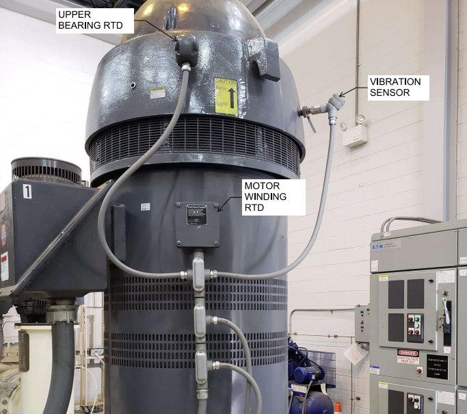
Winding temperature switches are commonly seen in smaller motors because they are a standard motor accessory offered by most vendors. Typically, for larger motors around 100 horsepower (HP) or greater, the owner may opt for a more expensive thermal protective sensor (RTDs). RTDs allow for a more flexible measuring of the temperature in the motor stator winding but requires an extra component to translate the temperature signals. Similar to RTDs, vibration sensors are also commonly paired with larger motors because spare motors of higher HP are not readily available for replacement and are not cost-effective to frequently replace. Figure 3 is a photo of an 800HP 4160V WP motor with vibration sensor and RTDs for a high service pump station.
Per the National Fire Protection Agency 70 (NFPA 70), more commonly known as the National Electric Code (NEC), Article 430.32 states that all continuous-duty motors are required to have (1) a separate overload device that will trip at different percentages, depending on the motor ratings, and (2) a thermal protector, or electronically protected, to prevent dangerous overheating.
Overload relays are typically a part of a magnetic motor controller, which are located upstream to the motor and are not necessarily considered a motor accessory. The overload relay for a magnetic motor controller is typically made of a bimetallic material or a melting alloy that opens the circuit if a current exceeds a set point or if the overload relay is heated over a period of time, which is indicative of an undersized motor. Therefore, in most cases, when a motor is controlled by a magnetic motor controller with overload relays, additional thermal sensors are not necessary because the overload relays have the capability for thermal memory retention and overcurrent tripping.
Per NEC Article 430.126, adjustable-speed drive systems or variable speed drive (VFD) systems are required to provide protection against motor over temperature conditions, and the protection must have the capability for thermal memory retention. Typically, VFDs do not have overload relays that can retain thermal memory. As such, additional thermal motor protective sensors and controls are required.
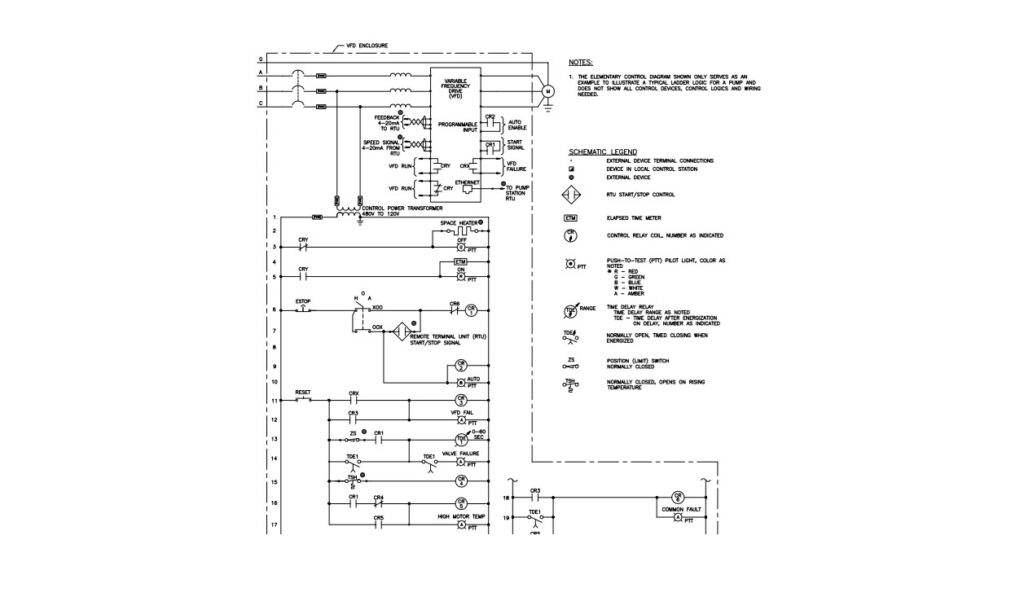
Figure 4 shows a control diagram for a booster pump pushing water from a wet well to a pipe with a check valve. Because the motor for the booster pump is only rated at 100HP 480V, RTDs and vibration sensors were not considered; however, since it is controlled by a VFD, the motor is required to have thermal protection (temperature winding switches). However, alarm and shutoff signals for RTDs and vibration sensors are usually represented in the control diagram as normally closed/normally open contacts from the sensor’s transmitter. The winding temperature switch (TSH) is in the motor and is a normally closed switch that only opens when the motor winding temperature increases. When the motor is energized and there are no alarms, control relay 1 (CR1) is energized, which means that all CR1 contacts in Figure 4 are shown as the opposite, and a start signal is sent to VFD to start the motor. If there are no motor winding temperature issues, TSH remains closed, which means control relay 4 (CR4) is energized and CR5 is deenergized because the normally closed contact for CR4 is now open owing to the energized state of CR4. When the motor is overheating, either due to overloading or other issues, TSH will open, thus deenergizing CR4. If CR4 is deenergized, the normally closed contact for CR4 will close and energize CR5. CR5’s normally open contact will close when CR5 is energized and will cause CR6 to be energized. This will open the CR6 contact upstream of CR1 on Line 6, thus opening the start signal to the VFD and causing the motor to shut off.
Knowing various motor enclosures and the motor protective sensors can help with water/wastewater treatment facilities and other rugged environmental motor applications.
Joshua Hunter, PE, and Lilly Vang, PE, are professional electrical engineers at CDM Smith, Denver, Colorado. Edited by Mark T. Hoske, editor-in-chief, Control Engineering, WTWH Media, [email protected].
Keywords
Industrial motor enclosures, motor protection devices
Consider this
Are you specifying the right motor enclosure and sensors for the application?
You also might like
Smart control systems: Make your AI/ML integration roadmap
See more from Control Engineering about motors and drives.