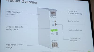
A control system relies on reliable power sources like an uninterruptable power supply (UPS) to achieve availability, protect equipment during power disturbances, preserve data, and support safe shutdown.
UPS applications for reliable automation insights
- How power quality affects control system reliability.
- Importance of UPS systems within industrial automation architecture.
- Practical methods to select, size and integrate UPS systems for PLC, SCADA and network infrastructure.
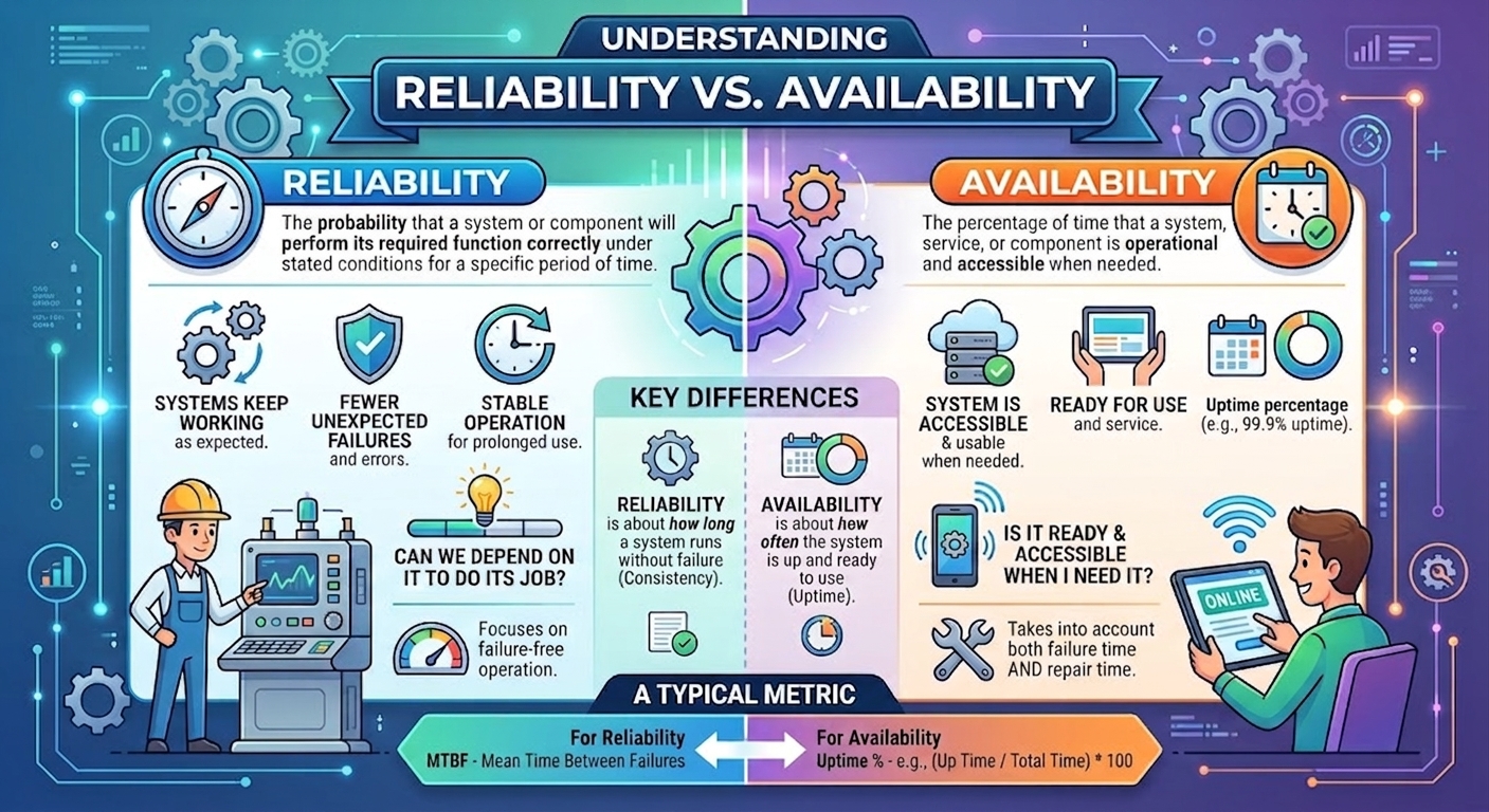
Reliability is a critical characteristic of industrial control systems. Control system reliability is the ability of the automation system (programmable logic controller [PLC], supervisory control and data acquisition [SCADA], instrumentation, and network) to consistently perform intended control, monitoring, and safety functions without interruption or failure under normal and abnormal operating conditions for a defined period.
Reliability is often confused with availability or uptime. Availability is the probability that a device is operating successfully when needed and is operated within specified limits. Uptime or availability is the percentage of time a system is available and operating. For example, a PLC system operating for 8,758 hours out of 8,760 hours per year has 99.98% uptime.
Reliability is always a function of failure rates and operating time intervals. Availability is a function of failure rates and repair rates. Uptime shows us how often the system is available, whereas reliability lets us know how likely the system is to operate without failing.
Reliability metrics consider frequency of failures, failure modes, recovery time, system design, redundancy, and maintenance practices.
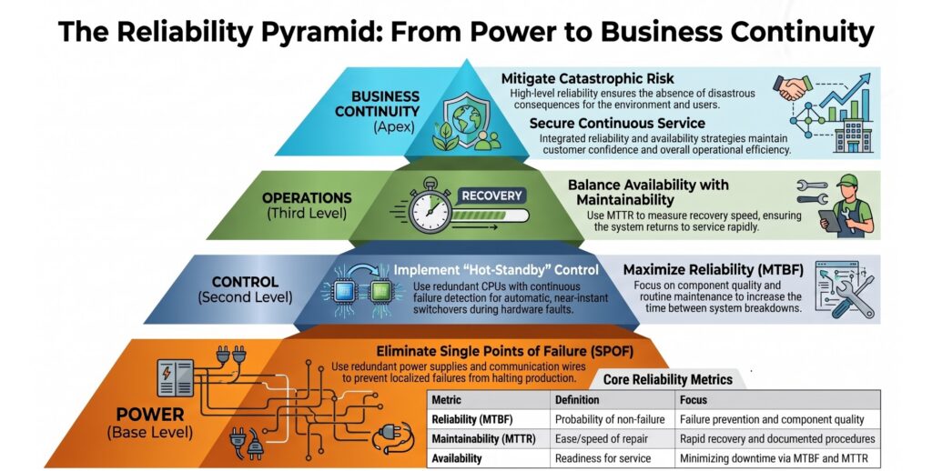
Two systems can have same uptime but different reliability. If a PLC system loses power 20 times a month and each outage only lasts for 30 seconds, annual uptime is still greater than 99.99%, but operators will face frequent interruptions, equipment may repeatedly reboot, and data may be lost. This is an example of high uptime and poor reliability.
Another system uses PLC-uninterruptable power supply (UPS) system architecture incorporating online double-conversion UPS, redundant power supplies, adequately sized batteries, and surge protection. The uptime of this system will be identical to the first system, but predictable and rare failures make it more reliable. This is an example of high reliability and high uptime.
Uptime is a result; reliability is a design philosophy.
Uptime measures how long an automation system is available, whereas reliability measures the ability of the system to perform its intended function without failure. The UPS contributes to both by preventing power disturbances from causing control system interruptions, data loss, and unsafe process conditions.
Why use uninterruptable power supply
The UPS is critical to condition and maintain a constant source of power to allow the control system to maintain control, protect equipment, preserve data, and support safe shutdowns during power disturbances. In industrial and infrastructure automation (water/wastewater, power, manufacturing), the UPS is part of the control system’s reliability layer, not just backup power.
UPS systems protect industrial automation equipment from momentary outages, voltage sags, voltage swells, and frequency disturbances that can cause PLCs, SCADA systems, and network devices to reboot unexpectedly. The UPS also provides additional protection against power surges. Power surges could potentially damage equipment beyond just unscheduled reboots.
The momentary outages are commonly caused by utility switching operations, electrical faults, lightning events, recloser actions, and generator transfer sequences. Although the interruption may last only a few cycles or seconds, it can cause control system reboots, communication failures, loss of alarms, and data corruption. The UPS supplies stored energy from its batteries until utility power is restored or standby generation is available.
Voltage sags and swells are among the most common power quality disturbances affecting industrial automation systems. A voltage sag is a temporary reduction in supply voltage that can cause PLCs, remote inputs/outputs, network switches, and SCADA equipment to reset or lose communications. A voltage swell is a temporary increase in voltage that can stress power supplies and damage sensitive electronic equipment. The UPS regulates incoming power and provides stored energy during power disturbances to maintain a stable output voltage to critical control equipment, preventing nuisance trips, data loss, and loss of process control.
Frequency disturbances occur when the utility or generator frequency deviates from its nominal value because of generation and load imbalances, generator instability, or power system faults. Excessive frequency deviations can cause power supplies to operate outside their design limits, potentially resulting in resets, communication failures, or unexpected reboots of PLCs, SCADA servers, network switches, and communication equipment. The UPS isolates automation equipment from these disturbances by delivering a stable output voltage and frequency regardless of incoming power conditions.
By maintaining stable power during these events, the UPS preserves process control, prevents loss of alarms and operational visibility, protects control systems from corruption or loss of critical data, and allows sufficient time for standby generators to start or for systems to perform an orderly shutdown. As a result, the UPS plays a key role in improving the reliability, availability, and safety of industrial control systems.
Automation loads are deterministic and safety driven. UPS design must match the control system requirements and behavior.
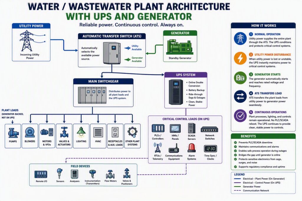
The UPS sits between the facility power system and the automation system, providing a buffer that isolates PLCs, SCADA servers, human machine interfaces (HMIs), network infrastructure, and control power supplies from power disturbances. The purpose of the UPS is not to keep the entire facility operating. The UPS provides power to critical low-power devices like PLC and SCADA servers and critical instrumentation to monitor and control plant operation during main power disturbances. The UPS is not designed or employed to power motors, variable frequency drives (VFDs), motor control center (MCC) buckets, heaters or large actuators.
Uninterruptable power supply sizing
UPS design starts with the consideration of load, the equipment that will be powered by UPS and their power requirements. A UPS is generally rated in volt-ampere (VA), and electrical load is normally measured in watts (W). The UPS power load in W is converted to VA.
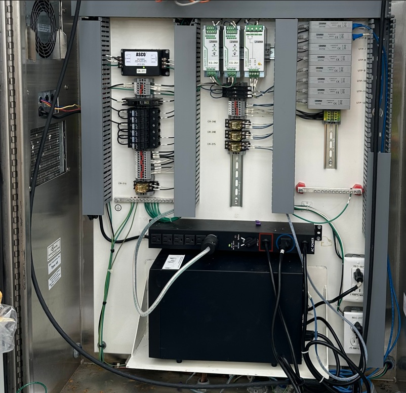
The following discussion highlights single-phase low-voltage loads and includes a single-phase UPS that can be mounted inside a control panel enclosure or can be rack mounted in server racks. Some plants prefer to have a stand-alone UPS supplying various loads as shown in Figure 3.
Before delving into calculations, the following discussion highlights the key criteria and terms used in UPS sizing.
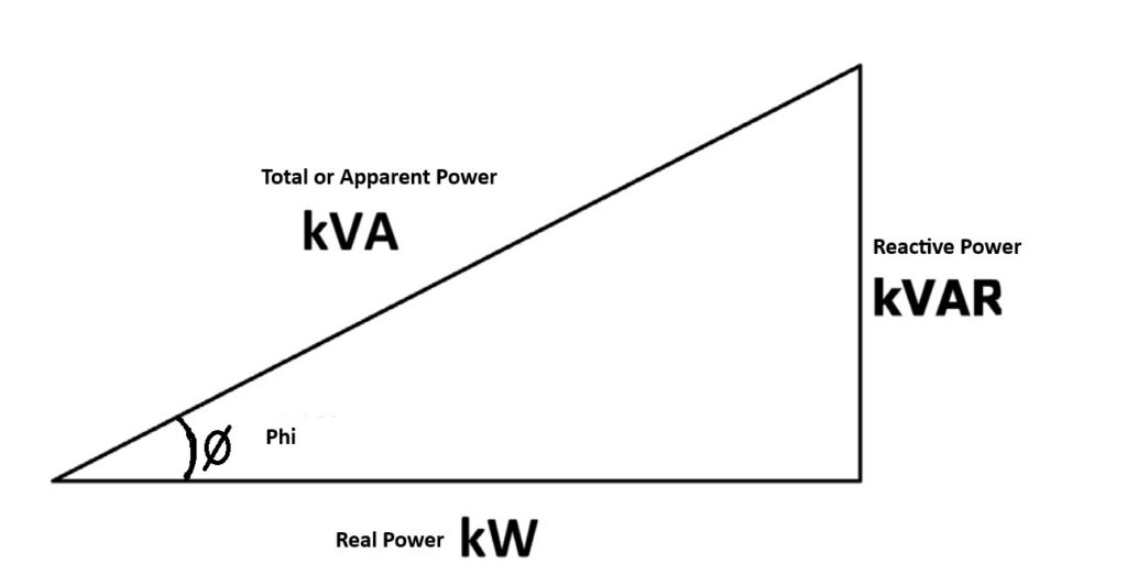
The power relationship in alternating current (AC) power is called the power triangle. The horizontal leg of the power triangle represents real power or actual power in W or kilowatts (kW). The vertical leg of the power triangle represents reactive power in volt ampere reactive (VAR) or kilovolt ampere reactive (kVAR). Reactive power is physically present, but it does not do real work. For example, in the case of AC induction motors, reactive power is the power that magnetizes the motor windings and helps the motor start and develop running torque. The hypotenuse of the triangle is the total or apparent power in kilovolt amperes (kVA).
The power triangle is a right-angle triangle, and the relationship between the kW, kVAR, and kVA is given by the Pythagorean theorem: (kW)² + (kVAR)² =(kVA)²
Power factor: The ratio of actual power (kW) to apparent power (kVA) is power factor. Power factor is represented as Cos Phi (Cos Φ) or PF. Φ is the angle between the horizontal leg and hypotenuse of the power triangle.
PF = kW/kVA = (Cos Φ)
This equation signifies that a smaller value of Φ will result in a better power factor. Also, a smaller value of Φ means smaller reactive power; hence, more useful power is available for the system.
In a direct current (DC) power system, there is no reactive power; thus, there is no power triangle. For DC power systems, the power factor is always 1.0 or 100%.
Sizing the UPS is a simple five-step process:
1. Calculate the actual connected load to the UPS.
2. Convert W to VA using power factor.
3. Add 25% to 30% spare load capacity.
4. Calculate the total UPS load and select the next larger standard UPS size available from manufacturer.
5. Determine the run time required for UPS. Check with manufacturer and determine the correct UPS size. Use the manufacturer’s run time chart at the expected load. Verify that run time at end-of-life batteries exceeds 15 minutes. Add external battery cabinets if additional run time is required.
Table 1: UPS sizing
| Load Description | Qty | Unit Load (W) | Total Load (W) | Design Load (W) |
|---|---|---|---|---|
| PLC Rack | 1 | 300 | 300 | 300 |
| Remote I/O Panels | 4 | 75 | 300 | 300 |
| SCADA Server | 1 | 600 | 600 | 600 |
| Ethernet Switches | 2 | 100 | 200 | 200 |
| HMI Workstations | 2 | 150 | 300 | 300 |
| Fiber Converters / Radios | 2 | 50 | 100 | 100 |
| Instrument Power Supplies | 2 | 75 | 150 | 150 |
| Miscellaneous Control Loads | 1 | 250 | 250 | 250 |
| Total Connected Load | 2,200 W | 2,200 W |
Table 1: Uninterruptable power supply sizing table. Courtesy: CDM Smith
Table 1 is a typical load list for a UPS in an industrial control system. The table includes SCADA server, HMI workstations, fiber converters, and miscellaneous control loads.
Table 2: UPS Sizing Calculation
| Parameter | Value |
|---|---|
| Total Connected Load | 2,200 W |
| Load Power Factor | 0.90 |
| Apparent Power (VA) | 2,200 / 0.90 = 2,444 VA |
| Spare Capacity (%) | 25% |
| Design VA | 2,444 × 1.25 = 3,055 VA |
| Recommended UPS Size | 3 kVA minimum |
| Preferred UPS Size (future expansion) | 5 kVA |
| UPS Topology | Online Double Conversion |
| Input Voltage | 120/208V AC or 480V AC (project dependent) |
| Output Voltage | 120V AC, 208V AC, or 120/240V AC |
| Runtime Target | 15-30 minutes (generator backed) |
| Runtime Target | 60+ minutes (no generator) |
Table 2: Uninterruptable power supply sizing calculation example. Courtesy: CDM Smith
Table 2 shows a typical example of UPS sizing calculations. In the given example, the calculated design VA is 3,055. The recommended size is the next larger size the manufacturer offers to meet maximum required VA and runtime requirements.
The actual VA rating, power consumption, or voltage and current of a device can be found on nameplate information and the datasheet provided by the device’s manufacturer. VA can be calculated by multiplying voltage and current for AC devices. For DC devices, multiplication of voltage and current will provide wattage of the device. Summing the VA or wattage ratings of all devices connected to the UPS will provide actual total load on UPS. Add spare capacity to the actual load by multiplying 1.25 or 1.30 with total actual load for 25% or 30% spare capacity.
Check this value with manufacturer’s standard offerings. Select the next higher available rating from the manufacturer’s standard. In the example, we have selected 5 kVA UPS, and the load with spare capacity was 3.005 kVA. This approach may lead to oversized UPS in some cases. The UPS sizing should be evaluated to meet the required load capacity and available run time if external batteries are not being used for the application. Many UPS manufacturers also offer some sizing software on their websites, and application engineer support to confirm the size. It is good practice to consult with the manufacturer to confirm size, mounting requirements, and temperature requirements to gain the best performance out of UPS system.
Batteries for UPS
Discussion of run time cannot be completed without discussion of batteries. The UPS power rating (kVA) determines how much load can be supported, while the battery sizing determines how long the load can be supported. The run time of the UPS can be increased by adding external battery modules.
Battery capacity is denoted with ampere hours (Ah).
The rule-of-thumb formula to calculate run time is as follows, with battery capacity denoted with ampere hours (Ah):
Run time (hours)= (Battery Voltage [V]×Battery Capacity [Ah]×UPS Efficiency) / Load (W)
Here:
Battery Voltage = Total DC bus voltage
Battery Capacity = Battery bank capacity (Ah)
UPS Efficiency = Typically 0.85 to 0.95
Load = Actual load in W
The typical run time provided by the UPS for a facility with standby generators is 5 to 15 minutes, which is long enough to ride through utility disturbances and the generator start/transfer time.
Remote unmanned pump stations with critical loads may need longer run time like 30 to 60 minutes. Run time is a system requirement, and it should be discussed and accepted by end users based on their experience with utility transfer, the duration and frequency of power outages, and the criticality of operation.
If the run time is known, this rule of thumb can be used to calculate battery capacity (Ah). Once battery capacity is known, add a margin for degrading caused by aging and design criteria like temperature. Add 25% to 30% capacity to the calculated capacity.
Battery sizing is never done based on nameplate capacity only. Three important factors should be considered for battery sizing: battery aging factor, temperature derating, and end-of-life performance. Always size batteries for the minimum required run time at 80% usable capacity to overcome these factors.
Peukert’s effect and depth of discharge are two factors that establish run times may be lower than the capacity listed on the battery nameplate.
Peukert’s law describes how a battery’s effective capacity decreases as the rate of discharge increases. Named after Wilhelm Peukert, who formulated it in 1897, the law highlights high-drain devices drain lead-acid batteries much faster than standard rating calculations predict. When a high current is drawn from the UPS, the chemical reaction exhausts active material at the plate surface faster than new electrolyte can diffuse inward. The internal resistance spikes, voltage drops below the system cutoff threshold, and the UPS shuts down early, leaving unused chemical energy trapped inside.
The depth of discharge adjustment explains that power must be cut off well before the batteries are drained completely. To prevent permanent damage, most UPS systems cut off power before the battery reaches 0% capacity (typically at 80% discharge depth). Factor in an additional multiplier for realistic results.
Battery selection for an industrial UPS system should be based on reliability, maintenance requirements, environmental conditions, life-cycle cost, run time requirements, and facility criticality rather than battery cost alone.
Comparison of UPS battery technologies for industrial automation
The most common batteries used in industrial UPS systems are valve-regulated lead acid (VRLA) and lithium-ion (LiFePO₄). VRLA batteries continue to dominate because of their low initial cost, while lithium-ion batteries are increasingly specified for high-reliability automation applications because of their longer service life, reduced maintenance, and improved life-cycle economics. Flooded lead-acid batteries are also lead acid–type batteries that require liquid electrolyte and periodic maintenance. Nickel-cadmium (Ni-Cd) batteries are often overlooked in commercial UPS discussions but are widely used in utility and industrial environments with harsh operating conditions. Ni-Cd batteries are very tolerant of temperature variations and deep discharges but have high initial cost and environmental concerns because of cadmium.
Table 3: Comparison of battery technologies
| Criteria | AGM VRLA | GEL VRLA | Flooded Lead Acid (VLA) | Lithium-Ion (LiFePOâ) | Nickel-Cadmium (Ni-Cd) |
|---|---|---|---|---|---|
| Initial Cost | Low | Medium | Medium | High | High |
| Service Life | 3-5 years | 4-6 years | 10-20 years | 8-10+ years | 15-20+ years |
| Maintenance | Very Low | Very Low | High | Very Low | Medium |
| Footprint | Medium | Medium | Large | Small | Medium |
| Weight | Heavy | Heavy | Very Heavy | Light | Moderate |
| Charge Time | Moderate | Moderate | Slow | Fast | Fast |
| Deep Discharge Tolerance | Fair | Good | Good | Excellent | Excellent |
| High Temperature Performance | Poor | Better | Good | Excellent | Excellent |
| Battery Monitoring | Basic | Basic | Conventional | Advanced BMS | Conventional |
| Indoor Control Rooms | Excellent | Good | Fair | Excellent | Good |
| Outdoor Cabinets | Fair | Good | Poor | Excellent | Excellent |
| Remote Sites | Fair | Good | Poor | Excellent | Excellent |
| Large Centralized UPS | Limited | Limited | Excellent | Good | Excellent |
Table 3: Comparison of uninterruptable power supply battery technologies for industrial automation
Courtesy: CDM Smith
Table 3 shows a comparison between various battery types used in industrial automation systems.
Batteries are sensitive to ambient temperatures. Elevated temperatures in non-climate-controlled enclosures on factory floors can significantly reduce battery service life. UPS units in industrial panels should include adequate ventilation or climate control, particularly for online/double conversion units that dissipate more heat because of continuous conversion.
In corrosive environments (wastewater treatment and chemical facilities, for example), the UPS and its batteries may require conformal coated boards or installation within appropriately rated enclosures. Panel installations should follow applicable seismic and environmental requirements recommended by the manufacturer.
The UPS dissipates heat, and the heat load should be considered during control panel design. A UPS with smaller VA rating can be DIN rail mounted. A UPS rated 1.5 kVA and above needs to be supported and installed properly in the enclosure as this type is not available with the DIN rail mounting option. Mounting brackets must be designed to support the UPS while maintaining clearance around it for air flow to enhance cooling.
Topologies for UPS systems
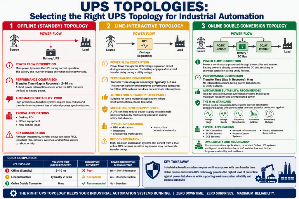
UPS topologies are critical design choices when selecting a UPS for a control system application. There are three topologies: offline, line interactive, and online double conversion. For industrial control systems, online double-conversion topology is best with zero transfer time to provide seamless power transfer. Online double-conversion UPS technology provides the highest level of protection against power disturbances while supporting maximum system reliability and process continuity. Figure 5 shows a comparison between the three topologies.
Redundancy and fail over for UPS systems
For critical systems, implement redundant (N+1) configurations (such as two UPS modules in parallel), each capable of carrying the full load. If one fails, the other seamlessly takes over. According to the Uptime Institute, there are several configurations to decide the appropriate tier level. Tier I facility protects against disruptions from human error, but not unexpected failure or outage. Tier II facilities cover redundant capacity components for power and cooling that provide better maintenance opportunities and safety against disruptions. A Tier III facility is concurrently maintainable with redundant components. Tier IV facility has several independent and physically isolated systems that provide redundant capacity components and distribution paths. Tier ratings are more significant for data centers. Tier IV is recommended for large data centers where failure or unavailability is not an option. Tier IV configuration consists of two parallel UPS systems that are individually backed up by a generator.
For common industrial control system applications, larger UPS units should include a maintenance bypass switch that allows power to route around the UPS (directly from mains to the load) during servicing so the UPS can be maintained without shutting down the protected equipment.
Centralized UPSs are wired to the distribution boxes. These distribution boxes feed UPS power to the critical load.
A panel-mounted UPS generally receives 120 VAC input and outputs 120 VAC to feed the panel’s internal power supplies. The power supplies feed the critical load. Power supplies are redundant in this case to ensure that failure of one power supply will not cause power outage to the critical load like PLCs and network switches.
A 24 Volt (V) DC UPS is encouraged because it eliminates DC to AC conversion in an online double-conversion UPS and losses caused by the conversion. A 24 VDC UPS module sits upstream of the PLC’s 24 V DC power supply. This is common for distributed I/O panels where a small DIN rail battery module ensures that the PLC never sees a dropout.
Integration with PLCs and SCADA systems
Once a UPS is selected, it needs to be properly integrated with the PLC, SCADA and control system. Integrating UPS systems into the control system architecture involves electrical integration (how the UPS is wired to equipment) and system integration (how the UPS status is monitored and used by the control system).
Another aspect of UPS integration involves the PLC and SCADA system monitoring the health of UPS. Most industrial-grade UPS systems provide dry contact outputs to communicate their status to the PLC for alarm generation. CDM Smith specifies wiring dry contacts from the UPS to the PLC to signal at least three conditions: low battery, UPS bypass, and UPS fault on the Process and instrumentation diagram (P&ID) and control descriptions. Also, the UPS indicates battery in operation status, load on inverter status, load on bypass status, AC input status, and the UPS malfunction alarm on the device itself.
For computer-based systems, UPS units connect via USB or network interface to the host to initiate shutdown when the battery is nearly depleted. SCADA/HMI run time on the UPS of 15 to 30 minutes is often paired with autoshutdown scripts that back up logs, close applications, and safely power down the operating system before battery exhaustion. This prevents database corruption and speeds recovery since the machine was properly shut down rather than abruptly de-energized.
Cybersecurity considerations for uninterruptable power supply
Modern UPS units frequently offer Ethernet communication via option cards for simple network management protocol (SNMP) or Modbus transmission control protocol (TCP) monitoring. However, connecting UPS units to the Ethernet network introduces cybersecurity and reliability risks. A network should be adequately segmented to prevent cybersecurity-related issues.
For most industrial control systems, only a few I/O points from the UPS are monitored, such as UPS/utility status, UPS alarm, and potentially UPS bypassed statuses. With only a few UPS status points to monitor, hardwired dry contacts typically provide sufficient visibility while avoiding the added cybersecurity and reliability risks of Ethernet connectivity. Using hardwired inputs eliminates a protocol compatibility or data mapping issue if the UPS is replaced with another make and model. In case Ethernet connectivity is a requirement, UPS devices can be placed on a separate maintenance network using virtual local area network (VLANs). Physical segmentation and restricting all the traffic outside the control system network will also reduce unwanted exposure.
Common UPS design mistakes to avoid
UPS design is critical for the reliability of control systems. The UPS design task needs collaboration between the end user, vendor, and designer. Common design mistakes to avoid are as follows:
- Oversizing the UPS but undersizing batteries
- Putting VFDs or solenoid power on the UPS
- No spare capacity
- No SCADA alarm integration
- Not allowing enough space for the UPS in control panels
- Not considering mounting requirements like DIN rail or shelf mounting
- Placing the UPS in hot MCC rooms or not considering ventilation and temperature control
- Not managing heat load in the control panel design as the UPS dissipates heat
- Placing the UPS in corrosive environment without taking precautions like conformal coating
- Ignoring battery replacement intervals
- Not training the operation staff adequately to maintain the UPS and replace and properly dispose of hazardous chemicals while working on battery banks.
Maintenance of UPS devices and systems
A UPS is not a fit and forget device. The most common UPS failure is inadequate maintenance, not design deficiency. This can be avoided by implementing a preventive maintenance schedule.
A preventive maintenance schedule should be implemented monthly, quarterly, and annually. Visually inspect, check alarms, review logs, verify operation, and check ambient temperature, fans, and air filters. Look for signs of battery swelling, leakage, or terminal corrosion as part of monthly maintenance.
Load bank test, battery test, system diagnostics, performance verification, string voltage checks, and infrared (IR) scan of terminations can be performed during quarterly maintenance. Comprehensive inspection, battery replacement (if needed), system calibration, documentation update, load test or conductance test, and cleaning of terminals can be part of annual maintenance.
Maintenance and timely replacement of batteries ensure uninterrupted service. VRLA batteries need replacement every 3 to 5 years. It is best practice to avoid mixing the age of batteries in parallel strings. Consider the effect of derating for age and temperature, take power factor into consideration when run time is calculated based on kVA demand, and provide airflow to cool down batteries as high temperatures deteriorate VRLA batteries quickly.
Training and contingency, UPS alarms
Operators and maintenance staff should understand how to interpret UPS alarms, check the battery status, and activate bypass switches. Commissioning should include simulated power failures to ensure all critical equipment stay powered; all alarms trigger, and autoshutdown scripts execute correctly.
UPS systems, the guardians of automation
UPS systems in industrial automation serve as guardians of control system uptime, ensuring that PLCs, SCADA servers, network infrastructure, and critical instrumentation remain powered through the electrical disturbances that inevitably occur in real-world industrial environments.
It is recommended that control system owners develop a standardized design and use it to ensure uniform application of the UPS throughout the plant.
A well-designed UPS system is a compliance-critical asset that protects production continuity, equipment integrity, personnel safety, and data reliability. Using a UPS reduces downtime, prevents equipment damage, mitigates safety hazards, and safeguards controls, data, and product quality across manufacturing environments. Starting from an accurate load assessment, selecting the right topology and redundancy level, accommodating real-world load behaviors, adhering to industry standards International Electrotechnical Commission (IEC)/National fire protection association (NFPA)/Institute of electrical and electronics engineers (IEEE)/ Underwriters laboratory (UL) standards, and implementing a disciplined maintenance program will ensure a UPS delivers reliable protection throughout its service life.
Prerna Bhatnagar, PE, CAP, CDM Smith, focused on instrumentation and control, Atlanta, Georgia. Edited by Mark T. Hoske, editor-in-chief, Control Engineering, Arrowfly, [email protected].
Keywords
Uninterruptible power supply, UPS, reliable automation power
Consider this
Is lack of reliable power your bottleneck to reliable automation?
You also might like
https://www.controleng.com/motors-drives/power
Other tutorials from CDM Smith include:
How to rethink automation through design, practical engineering