Custom algorithm used to solve challenges with robotic layer forming and de-tray system
AMT and Gojo Industries, Inc. worked together to create two robotic cells to function in part with their conveyor system, a de-tray operation and a layer forming system.
Learning Objectives
- Applied Manufacturing Technologies (AMT) worked with Gojo Industries to create robotic cells: a de-tray and layer forming system.
- There were conveyor alignment issues, which caused challenges during the implementation process for the project.
- Designing the de-tray and layer forming robotic cells allowed several the engineering team to solve robot speed issues and meet cycle time requirements.
Applied Manufacturing Technologies (AMT) worked with Gojo Industries to create robotic cells: a de-tray and layer forming system. To aid in vision issues on the de-tray system, they used 3D snaps, which is a method that generates 3D point cloud. Engineers restricted the movement of the robots to help increase its speed. On the layer forming side, engineers used a camera above the conveyor so that any box can get through. To solve the speed issue, the conveyor used its rails to align boxes and increase speed.
Project summary
The robotic de-tray system was set up to receive trays of product (one-layer, homogenous SKU). A database supplied information about each tray, including the box length, width, height, weight and expected orientation, as well as how many rows and columns make up a single tray. Using an overhead 3D vision system and programmable logic controller (PLC) to find all the boxes on the tray and a custom algorithm to determine which boxes to pick up, the robot arm moves to the target boxes, uses a vacuum gripper to pick them up and moves to an outfeed lane to drop them off. Boxes must leave the machine in single file with their length along the conveyor flow direction.
The robotic layer forming system receives individual cases from a metered infeed conveyor lane along with a set of data describing each box. An overhead 2D camera finds each box on the conveyor as it comes in. Using an encoder that measures the motion of the conveyor belt, the robot moves a gripping tool around each incoming box, squeezes to hold it and moves it on the conveyor belt so that together with the other boxes on the conveyor, it will form a grid pattern at its destination.
Dealing with conveyor alignment issues
Some of the difficulties that arose during this project included preparing for poorly aligned boxes on the conveyor, creating the logic to lump boxes into pickable groups, preventing damage to boxes from the gripper squeezing too tightly and inefficient tray patterns. Even further, this system was designed during the COVID-19 pandemic and met strenuous post-COVID challenges, including supply chain shortages, laborious facility preparations, and lack of product availability.

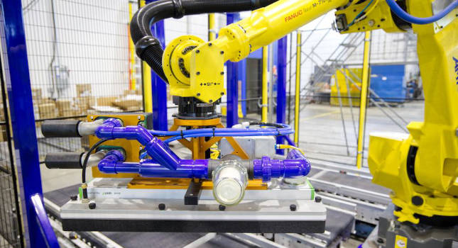
Customization of the program limited the allowable acceleration, preventing loss of vacuum on susceptible boxes. Courtesy: Applied Manufacturing Technologies (AMT)
De-tray machine limitations
The de-tray machine ran into limitations with the vision software while attempting to identify and unload the boxes. No matter how perfect the grid packing was at the start, vibration, slipping, bouncing, and other forces would shift the boxes around — it’s improbable that the boxes would stay in perfect grid formation when they got to the robot. With no way to find the edges between boxes, the 3D point cloud, a spatial representation of the corners of the boxes, was interpreting multiple boxes as a single blob and the typical 2D image with the same camera can malfunction when there are too many edges found in the picture. The process became very slow and frequently found edges that would make a correctly sized box, even if there was no box there.
Layer forming system
Although more straightforward than the de-tray system, the layer forming cell also had its challenges. The most pressing obstacle was speed. The required cycle time mandated that this machine needed to handle a box every 1.1 seconds. The early simulations showed that it would not be sustainable to make this model of robot move that quickly. The robot could reach those rates but not sustain them; it would have to overdrive all the motors to an unhealthy level, greatly shortening its lifespan
Solution
In-depth research was conducted on the capabilities of the 3D vision system and learning about using it to find rectangular boxes. This vision system uses a off-the-shelf software called box locator tool. Depending on the type of load parameters, the robot’s speeds and accelerations had to be adjusted to handle loads with diverse conditions, orientations, weights and heights.

A custom algorithm was used to determine which boxes to pick up. Courtesy: Applied Manufacturing Technologies (AMT)
De-tray system
To meet the twin challenges of the vision system not finding the boxes and meeting the speed requirements, the engineers experimented with a variety of options before settling on a strategy.
To tackle the vision issues, 3D snaps were utilized, a process that generates a 3D point cloud. Filters were also added to this data, such as removing all points that are below a certain Z height. By knowing what the minimum box height is and that other obstacles are below that height, the Z value is determined, and everything can be removed from this point cloud except for actual boxes. To avoid one big blob when multiple boxes are present, 2D images are used to find all the possible spots that a box could be, and then remove any of them that didn’t have enough 3D points within them to be a real box. Through this process all boxes on the tray can be successfully found with an accurate position and orientation for them.
The most time-consuming task for this project was writing the custom software logic to use the vision system to lump boxes together into pickable groups for the de-tray machine. The algorithm to find the best box to focus on consisted of sorting all results in the Y direction, so that the first box on the list was the farthest away from the robot. If any blockers (a box that was in the way when trying to pick up the box #1) are found, that means box #1 is not the best to focus on, and the process was repeated trying box #2 as the focus. After finding the focus box to pick up, the question became can any other boxes be picked up with it?
After electing a percentage that the boxes needed to be overlapping to be considered aligned and can be picked together to find the group, came the calculations of where to put the foam pad. The objective is to land the edge of the foam right on the edge of the group, so that it only got the boxes that it wanted and no extras. When the group has been selected, the required location of the vacuum pad is determined, and the robot path is mapped from the boxes to the outfeed.
Several optimizations were employed to speed up the cycle time. These included using a lower resolution image with a sharpen filter, restricting the flexibility of the length/width dimension matching, lowering the density of the search, changing the exposure, and more. With these adjustments, the vision process was running at the required speed. To speed up the robot, the engineers wrote the program to limit the height of the robot arm to the minimum required for clearance. The proximity of the infeed and outfeed lanes plus the restricted robot movement meant that the cycle time could be met. A final customization to the program limited the allowable acceleration based on a box’s surface area, height and weight, preventing loss of vacuum on susceptible boxes.

An overhead 2D camera communicated with the PLC to find the box on the conveyor. Courtesy: Applied Manufacturing Technologies (AMT)
Layer forming system
On the layer forming system, an overhead 2D camera communicated with a PLC to find the box on the conveyor as it comes in, so the machine can handle boxes that aren’t aligned to a datum. The robot also uses an encoder that measures the motion of the conveyor belt. Using these devices and line tracking with an encoder to measure speed and movement, the robot moves a 7th axis gripper around each incoming box, squeezes to hold it, and then slides it along the belt. The robot puts each box in a position to form a grid pattern when collected at the end.
The full sequence is below:
-
Wait for the photo eye to see a box arriving.
-
Store the current encoder counts to remember where the belt was when the box arrived.
-
Trigger the overhead camera to take a picture and get the position/rotation of the box.
-
Wait for the belt to move far enough that the box is within the robot reach.
-
The robot meets the box, grabs it, and slides it into the final position while matching the conveyor belt speed.
Once the robot finishes a layer’s worth of boxes, it resets and starts over for the next layer. The data also indicates if a box is supposed to end up with its length aligned to the conveyor flow or turn 90 degrees. The robot can calculate all the moves at runtime with this amount of data.
To solve the speed issue, the engineers came up with the ingenious idea to use the conveyor’s incoming guide rail to best advantage.
The rail was referenced as a baseline location and three rows of boxes were placed in the proper position to form the required pattern at the end. Since one-third of the boxes came onto the conveyor properly positioned at the rail, only two-thirds needed to be moved, saving time and meeting the 1.1 second throughput requirement without putting the robot above its sustainable capacity.
Conclusion
In designing the de-tray and layer forming robotic cells, the engineers solved several high-level technical challenges, including writing a new program for the 3D vision system and creatively solving robot speed issues to meet cycle time requirements.
Michael Horth is a senior controls engineer at Applied Manufacturing Technologies, a CFE Media and Technology content partner. Edited by Chris Vavra, web content manager, CFE Media and Technology, cvavra@cfemedia.com.
MORE ANSWERS
Keywords: machine vision, discrete manufacturing
CONSIDER THIS
How can 3D vision improve your manufacturing operations?
Do you have experience and expertise with the topics mentioned in this content? You should consider contributing to our CFE Media editorial team and getting the recognition you and your company deserve. Click here to start this process.