Editor's note: "Integrator Update" is an occasional department examining an application from a system integrator's viewpoint.Total Systems Design (TSD) (Exton, Pa.) recently integrated the controls for a Basic Oxygen Furnace (BOF) Hood Cooling System at Bethlehem Steel Corp.'s Sparrows Point facility.
Total Systems Design (TSD) (Exton, Pa.) recently integrated the controls for a Basic Oxygen Furnace (BOF) Hood Cooling System at Bethlehem Steel Corp.’s Sparrows Point facility.
The system is a PLC-controlled, closed-loop, cooling water system. In the system, the heat generated is removed from the water through use of air-cooled Heat Exchangers (HEXs); each having a set of two variable-frequency drive (VFD) fans. Each Oxygen Furnace batch (Heat) lasts about 25 minutes. During the Heat, the temperature rises from a minimum to a maximum, achieves steady state, and then drops back to the minimum.
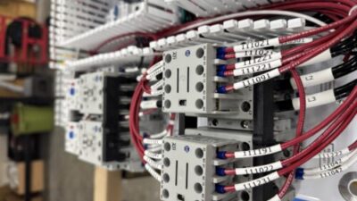
Ten HEXs are available for use in the system. Six or eight are placed in Automatic, with one in Standby. Each HEX can be isolated from the system through use of an inlet isolation valve. When a HEX is on line (in Automatic), the valve is open and the fan speeds are controlled by the PLC. Although HEXs may be on line with water flowing through them, if the temperature is low enough, the HEX fans may not be running. The first image shows a view from beneath a HEX fan.
A feed-forward scheme is used to calculate the HEX fan speeds based on the heat to be removed, the number of HEXs in Automatic, HEX air inlet temperature, and HEX fouling factor. The original system design had the HEX VFDs restricted to an operating range of 10-100% of rated speed (e.g., &10% rated speed, speed set to zero). Using this scheme, the fans (for the HEXs in Automatic) effectively start and stop as a bank.
Delay compensation
One problem encountered was that the heat source is in a separate building several hundred yards from the HEXs. When the water temperature changes at the heat source, it takes approximately 60 seconds for this change to reach the HEXs. To prevent problems with cooling, the fan speed signal had to be delayed to allow the change in speed to occur the same time the temperature change reaches the HEXs.
A sub-routine was created to delay each calculated speed signal and send it to the individual fan set control files, which then make the determination whether or not to ‘allow’ the speed signal to pass to the VFD (e.g., in Automatic, >10%). The delay method developed was extremely helpful during Site Acceptance Testing because the delay could be changed to fine-tune the system response. The delay sub-routine also allows standby HEX to be brought on line with the fans at (or near) the correct (and delayed) speed.
During commissioning, the VFD OEM informed the project team that the VFDs were restricted to an operating range of 25-100%. The program was changed and commissioning successfully completed. With the HEX fans starting and stopping as a bank, residual heat was being built up in the heat source before the calculated speed rose above 25% and remained at the end of a Heat once the speed dropped below 25%.
Residual heat
The residual heat created significant hot spots in the cooling panels that remove the heat from the heat source. These hot spots were shortening the life of the equipment, and created the potential for material failure (and plant shutdown).
A post-commissioning modification to start and stop HEX fan sets sequentially, rather than starting or stopping the fan sets as a bank solved the hot-spot problem. This modification was implemented with no loss of production time. Once implemented, the sequential (versus bank) starting and stopping of fan sets lowered the cooling panel temperatures by up to 20 °F.
Integrator: Total Systems Design, Exton, Pa., www.totalsystemsdesign.com (contact Neal Collier), is a member of the Control System Integrator Association, www.controlsys.org .
For more information, visit www.controleng.com/freeinfo .


