Part 3 tutorial: Understanding the operation of closed-transition synchronous transfer and its significance in improving reliability and power quality.
Learning Objectives
- Receive background on medium-voltage drives and tutorial on motor physics provide needed information for optimization of motor-drive systems.
- Understand that reducing starting current can extend a motor’s useful life span and synchronous transfer can save medium-voltage motor and drives resources and assets.
- Learn about how a three-motor synchronous transfer motor-starting application works, explained with diagrams and text.
Medium-voltage motor-starting, VFD insights
- Background on medium-voltage drives and tutorial on motor physics provide needed information for optimization of motor-drive systems.
- Reducing starting current can extend a motor’s useful life span and synchronous transfer can save medium-voltage motor and drives resources and assets.
- Three-motor synchronous transfer motor-starting application is explained with diagrams.
Electric motors play a critical role in nearly every modern industrial application, and engineers naturally focus on the specifics of the mechanical work that is to be performed. Objective specifications often are driven by the torque profile of the load, the precision required by the application, and the allowable energy consumption. Industrial motors may be run across-the-line (switched on-off) when speed and torque control is not required. Variable frequency drives (VFDs) provide a much greater level of speed and torque control when required, and generally minimize mechanical and electrical stresses on a motor system.
As important as motor operating characteristics are for a given application, it is no less important to consider motor-starting characteristics. The first few seconds of starting a medium voltage (MV) induction motor can present significant challenges.
ONLINE
-
View part 1 of this series: How to choose a VFD for medium-voltage motors
-
View part 2 of this series: Power quality, harmonics: How to select a variable frequency drive (VFD)
Motor background: Tutorial on motor physics
An induction motor is comprised of two sets of conductor coils. The stator coils (fixed “motor windings”), are perhaps the most intuitive, because they are the connections with which we interact. The rotor coils (rotating) are less intuitive. The rotor is a cylinder comprised of conductive bars (resembling a “squirrel cage” or hamster wheel) that rotates inside the stator (with no external electrical connection).
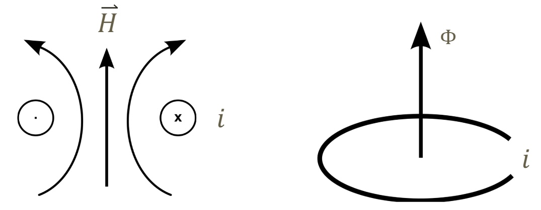
To understand the physics behind an induction motor, consider the following two statements noted in Figure 1:
When electric current travels around a circular coil, a perpendicular magnetic field is induced.
When a magnetic flux passes through a conductive coil, a current is induced in the coil.
Current induces magnetism. Magnetism induces current.
When rated voltage is initially applied to the stator coil, the initial impedance of the coil is low, which results in a large current (Current = Voltage/Impedance). This relatively high stator current induces a proportionally strong magnetic field. The magnetic field passes through the air gap to the rotor coils, inducing current to circulate in the rotor coils. Just as circulating stator current induced a magnetic field, the newly induced current in the rotor coils induces its own opposing field. The interaction of these magnetic forces results in a torque applied to the rotor shaft. As the rotor speed increases, so does the Back EMF voltage. [Here, EMF stands for electro-motive force.] The increasing back EMF counters the applied voltage, reducing the effective voltage seen by the stator coil. Reducing the effective stator voltage in turn reduces the stator current, which reduces the magnetic field induced by the stator current, which reduces the induced current in the rotor, resulting in a reduction of the rotor field. As the motor reaches rated speed, stator and rotor currents decrease until they reach steady state operating conditions.
During this process, until the motor reaches rated speed, typical MV motor starting currents may be 5 to 7 times greater than steady state rated full-load current.
Starting current creates significant mechanical and thermal stresses on the motor windings and rotor coils. For this reason, many large motors are designed and specified for a limited number of starts per hour. Restricting the number of starts allows the rotor to return to an acceptable temperature before continuing steady-state operation. It is important to note that motor RTDs (resistance temperature detectors) monitor the stator coil temperature. There is typically no direct means to measure the rotor coil temperatures.
Across the line starting current also creates a significant stress on the power supply. On a 5000 HP motor, starting current may represent 30 MVA of load on the power system. Depending on the capacity and impedance of the utility supply transformer, this starting load may result in a significant supply voltage drop, impacting other users on the power system, and potentially triggering the utility to impose financial penalties.
Reducing starting current to extend a motor’s useful life span
Reduced voltage starters (RVS) and reduced voltage soft starters (RVSS) provide a traditional means of reducing harmful motor starting currents. These devices switch large resistor arrays or autotransformers in series with the motor or use semiconductor switching devices, to reduce the available voltage during start. Once the motor is started, the reduced voltage device is isolated, and full line voltage is switched to the motor.
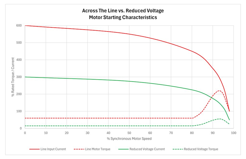
Ohm’s law dictates that current is proportional to voltage. Using an RVS device to reduce starting voltage by 50% will result in a corresponding current reduction of approximately 50%. While this represents a significant reduction compared to 600% across the line starting current, 300% starting current will still have a negative impact on motor heating and starting duty, and still places a significant starting load on the power distribution system.
Another consideration of reduced voltage solutions is the impact on available starting torque. As starting voltage is reduced, the available starting torque is reduced proportionally to the square of the reduction in voltage. For example, reducing voltage to 50% results in a reduction of starting torque to (50%)2 = 25% of rated starting torque. See Figure 2. When implementing a reduced voltage starting solution, it is critical to evaluate the required load torque. If the reduced pullup torque is insufficient to accelerate the load, the motor will stall. Mechanical systems may be employed to disengage the load during starting, but not without adding additional cost and complexity.
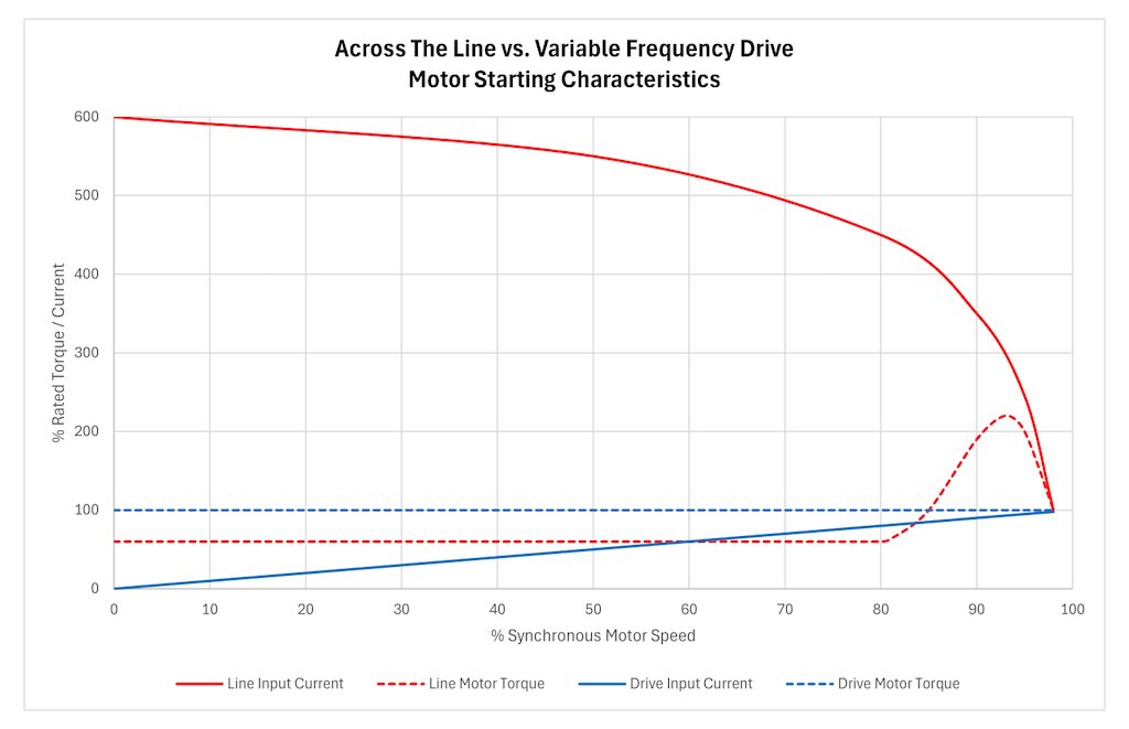
VFDs provide an ideal solution to manage motor starting. Unlike a reduced voltage starter, which can only control the applied voltage, VFDs can adjust both the applied voltage and the applied frequency for optimal motor performance. By maintaining the optimal ratio of voltage to frequency (V/Hz), a VFD can start a motor at 100% rated current, while producing 100% rated torque throughout the speed range.
This operational efficiency improvement allows a VFD-controlled motor to produce greater starting torque than the same motor could produce started on the line, while eliminating the motor thermal stress, mechanical stress and system voltage drops associated with line started motors and RVS solutions (Figure 3). In many applications, a VFD is the only acceptable means to start a large medium-voltage motor on the existing utility supply.
The only potential disadvantage of using a VFD for medium-voltage motor starting is cost. In applications that do not require speed or torque control, using multiple VFDs to operate multiple MV motors can be cost prohibitive. For these applications, synchronous transfer provides a means to use one VFD to efficiently start multiple motors, smoothly transferring each motor to utility line power once steady-state operation is reached.
Synchronous transfer: How it works with motors and drives
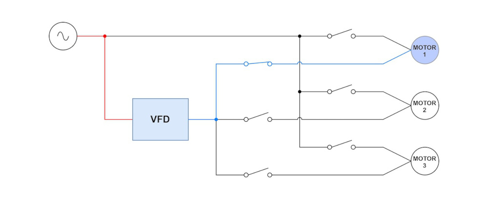
In a medium voltage closed transition synchronous transfer, a variable frequency drive is used to start and accelerate a motor as shown by the blue lines in Figure 3. Once full 60Hz rated motor speed is achieved, the drive synchronizes the voltage and frequency of its output precisely with the voltage and frequency of the utility supplied line power. When the waveforms match, a contactor is closed to connect the utility supply to the VFD output. Since the voltage and phase have been synchronized, essentially no current flows between the line and the VFD, while both provide current to the motor. After a brief (closed transition) period of synchronous operation with both sources connected, the VFD output is switched off, and a second contactor opens to isolate the VFD from the circuit, leaving the motor connected solely to utility power. Once isolated from the first motor, the VFD is available to operate other motors, while the first motor continues to operate on utility line power.
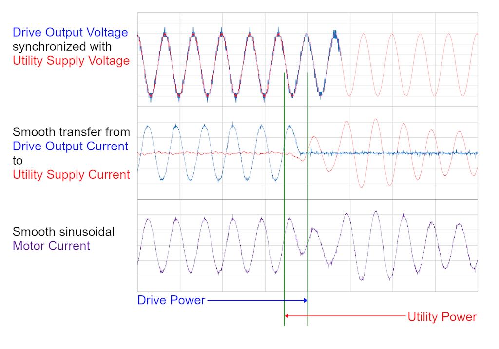
This is referred to as a “closed” transition because the drive synchronizes the magnitude and phase of the utility supply to its own output so precisely that both are connected simultaneously during the “make-before-break” transition (the period in which “drive power” and “utility power” overlap in Figure 4). It is important to distinguish a closed transition transfer from an “open” transition or “bypass” sequence. In an open “break-before-make” transition, the drive accelerates the motor to speed, but then simply disconnects, allowing the motor to spin uncontrolled until the utility line contactor closes, completing the open transition to the line. Because magnitude and phase are not synchronized and controlled, closing the bypass contactor during an open transition will create a significant mechanical torque transient as the utility supply attempts to pull the motor into sync, as well as corresponding current transients that may result in upstream overcurrent trips or unacceptable supply voltage drop.
Three-motor synchronous transfer motor-starting application
Figure 5 illustrates the typical operation sequence for a three-motor synchronous transfer motor-starting application.
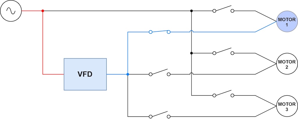
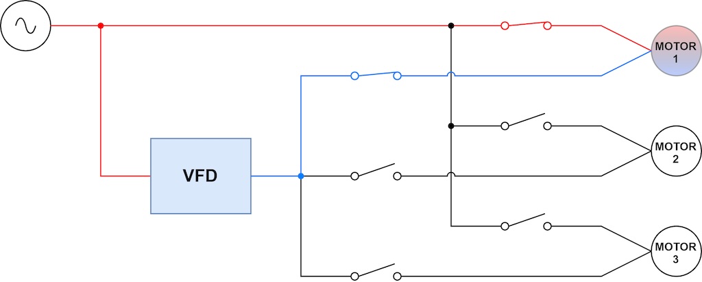
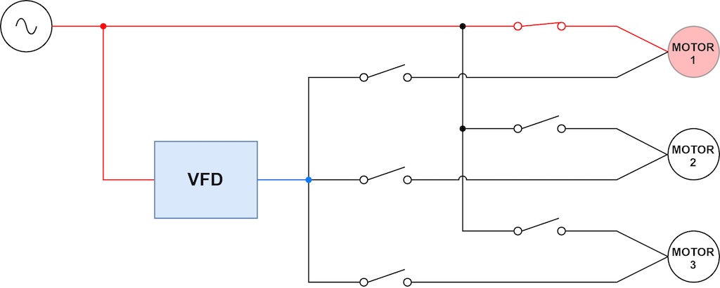
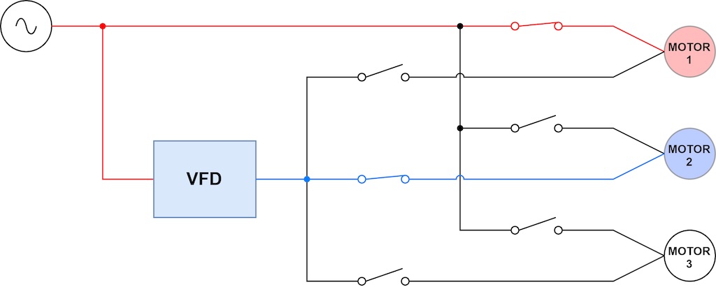
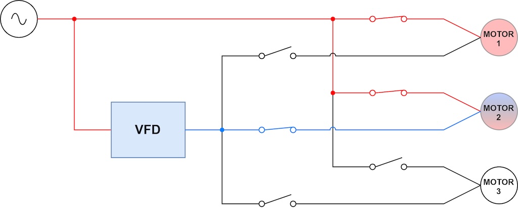
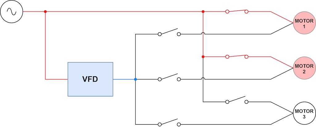
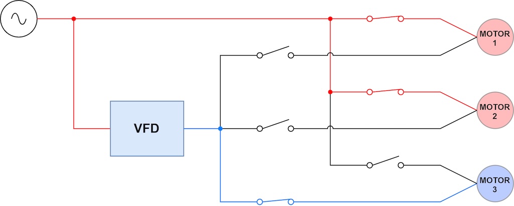
Closed-transition synchronous transfer provides a cost-effective means to smoothly start multiple medium voltage motors with one drive. Unlike traditional starting methods, the drive maintains full speed and torque control of the connected motor. For example, in Figure 5G, the application load may require motor 3 to be synchronized to the line, or it may require the VFD to maintain speed control. The control can be designed to operate as required by the load.
As the load is reduced, each of the sequences shown in Figure 5 may be reversed. Each motor may be smoothly synchronized back from utility to VFD control, decelerated, and isolated – effectively moving backward through Figures 5G-F-E-D-C-B and back to 5A.
Using this sequence, a drive equipped with closed transition synchronous transfer capability may be used to start multiple motors, while eliminating the motor thermal stress, motor mechanical stress, and system voltage drop problems associated with other starting methods. By transferring the motor to the line once accelerated, steady state operating efficiency is improved by eliminating the thermal losses associated with operating a drive at full load. Closed transition synchronous transfer combines the benefits of starting a motor with a drive with the benefits of operating a motor on the utility line.
Lucas Paruch is the senior development engineering manager for medium voltage drives at Yaskawa America Inc. Edited by Mark T. Hoske, editor-in-chief, Control Engineering, WTWH Media, [email protected].
KEYWORDS: Motors and drives, variable frequency drive (VFD) selection, medium-voltage motor starting tutorial
CONSIDER THIS
Are you optimizing assets with how you apply medium-voltage drives?
