With wireless transmitters, there are no wires to troubleshoot. If designed properly, the data goes from the transducer to the control via multiple wireless paths. Here’s how wireless communication is handled between wireless field devices and the host application.
Industrial wireless designs decrease network troubleshooting. “Follow the line.” That’s what our lab technician used to tell us when process data was not showing up on our system. We would follow the line, and sure enough we would discover either a poor connection or reversed wiring with one of our transducers. With wireless transmitters, there are no wires to follow. That’s the beauty of wireless technology. In fact, if designed properly, the data goes from the transducer to the control via multiple wireless paths.
This concept might frighten an instrumentation professional. However, this initial reaction is quickly replaced with enthusiasm after the first or second installation of a wireless field instrument system. To help dispel related fears, an overview of a wireless field instruments system follows, along with discussion of a sensor mesh network, how sensors communicate, and how the system ensures reliable radio communications among devices. Using the ISA100.11a field device network as an example, a general explanation follows on how wireless communication is handled between wireless field devices and the host application.
A wireless topology
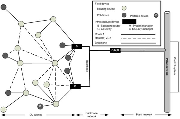
A traditional, wireless field-device network topology consists of wireless field devices and a wireless field device network manager. A field device could be an input/output (I/O or IO) device, such as a transmitter or an actuator, a wireless adaptor for a wired transmitter, or a backbone router device. I/O devices or wireless adaptors also can be configured as routers. They can transmit their own data and the data received from nearby wireless field devices. Many instrumentation professionals are familiar with input and output devices but not with wireless adaptors or backbone routers. A wireless adapter is a field device that can be connected to a wired device, instantly turning it into a wireless device.
Currently, wireless adapters are used to send diagnostics data from wired-HART devices that are not connected to HART I/O devices. A backbone router is a new type of field device introduced with the ISA100.11a standard. This field device encapsulates the data received by ISA100.11a devices and sends it over a backbone to the wireless field device manager. The wireless field device manager has two interfaces, an ISA100.11a and a backbone network interface. A backbone is a data network such as, but not limited to, industrial Ethernet, IEEE 802.11, or any other network within the facility.
A wireless field device network is managed by the wireless field device network manager, which acts as a system manager, security manager, and gateway.
The system manager governs the network, devices, and all communications. In the case of ISA100.11a devices, the network can be composed of multiple subnets. The security manager generates security keys and authenticates devices. It will also manage contracts between field devices ensuring that only authenticated devices can communicate with each other. Finally, the gateway provides an interface between the wireless field device and the plant network. The gateway will translate the data received from the wireless field devices to established field protocols (such as Modbus, HART, etc.) or proprietary protocols, such as those used for vibration signatures.
Field device addressing
An ISA100.11a field-device network uses an IPv6 over Low power Personal Area Network (6LoWPAN) network layer, which allows it to easily plug into an IP-capable backbone. When an ISA100.11a field device is authorized to join the ISA100.11a network, it is given a 128-bit IPv6 network address and a 16-bit data link subnet short address. Both addresses are allocated by the system manager. The 128-bit address uniquely identifies a device in the ISA100.11a network, and the 16-bit alias does the same within the ISA100.11a subnet. The 16-bit subnet address is only used within the subnet; once a message reaches the backbone, the full 128-bit IPv6 address is used.
Field device communications
All standard-based wireless field devices (ISA100.11a or WirelessHART) use radios compliant with IEEE 802.15.4-2006, which operate in the 2.4GHz band and permit frequency hopping across 16 direct sequence spread spectrum (DSSS) channels.
All standard devices support two-way communications, meaning they listen for incoming messages and send pending ones. So, if the 2.4 GHz bandwidth is being used by other devices (that is, Wi-Fi enabled devices), how do wireless field devices communicate with each other without conflict?
Channel hopping, timeslots
The ISA100.11a standard uses intelligent channel-hopping algorithms to manage interference from other RF devices and multipath rejection. Coexistence with other RF systems is improved by using different spectrums. Finally, the same algorithms ensure that frequencies with consistently poor performance are not used.
Each device uses specific timeslots while hopping between channels to communicate. A timeslot is one nonrepeating period of time with a duration that is configurable (range from 10 ms–15 ms). The timeslot duration is set by the system manager when a device joins the network. During these timeslots, the device can perform a set of operations, such as transmit, listen, wait, timeout, and acknowledge.
There are three modes of operations defined in the ISA100.11a standard: slotted channel hopping, slow channel hopping, and hybrid. Each mode provides ways to configure the series of timeslots.
Coexistence strategies
Several other strategies are used simultaneously to optimize coexistence with other users of the 2.4 GHz radio spectrum, particularly those based on WiFi:
- Leverage the backbone: Transmitting data to a high-quality backbone within one or two hops reduces the use of the ISA100.11a radio channel and improves reliability and latency.
- Timeslotted operation: Timeslotted operation and scheduled transmissions minimize collisions and communication retries within a subnet.
- Radio selection: IEEE 802.15.4:2006 radios and WiFi radios can transmit simultaneously without loss of data.
- Low duty cycle: Data transmissions are infrequent, keeping network overhead to a minimum.
- Staccato transmissions: ISA100.11a transmissions are very short (not bursts), enabling co-located WiFi networks to recover quickly in the event of lost packets.
- Time diversity: Configurable retry periods potentially spanning hundreds of milliseconds enable the system to coexist with other users of the spectrum that may need to use the band for high-priority bursts of activity.
- Channel diversity: The low duty cycle of the radio is spread across 16 channels, further reducing the worst-case opportunity for interference to a fraction of 1%.
- Spectrum management: The user can limit operation to certain radio channels.
- Adaptive channel hopping: The system can avoid problematic channels on a link-by-link basis, such as channels exhibiting WiFi cross-interference or persistent multipath fades.
- Collision avoidance: The 802.15.4 MAC supports CSMA.
Routing, nonrouting
In the ISA100.11a standard, field devices can be configured as routing or nonrouting devices.
A nonrouting device has no mechanism to route data received from other ISA100.11a devices. It will simply send its data to a routing device (either routing I/O or backbone router). This minimizes energy consumption and maximizes battery life. Nonrouting mode also improves message latency.
A routing device can route data from neighboring devices. A routing I/O device can route its own data in addition to data received from nearby wireless I/O devices. Devices with routing capability will typically be used to extend the range of an ISA100.11a network.
Routes management
The ISA100.11a standard supports two types of routing, graph and sourcing. Graph routing is managed by the system manager and is based on device-generated reports that indicate instantaneously the quality of wireless connectivity to neighboring devices. The system manager accumulates these signal quality reports to make routing decisions. Once the system manager makes its routing decisions, it then configures routes for each device in the network.
Source routing is handled at the transmitting device level. The device specifies the route that a packet should take through the subnet. When a source packet reaches the next receiving device, the route is examined to determine to which neighbor the message should be forwarded. Graph routing is the most efficient method of managing routes.
Intelligent field manager
You may not be able to “follow the line” any longer with wireless field devices, but you can certainly rely on the intelligence of the wireless field device manager to follow the line for you. Wireless standards, especially ISA100.11a, which has been designed for wireless communication, have taken the communication medium into consideration. These new wireless devices have the necessary built-in intelligence needed to continue communicating despite severe RF interferences.
Soroush Amidi is a product marketing manager for Honeywell Process Solutions. He manages several wireless solutions including OneWireless Network, Honeywell’s industrial wireless local area network. With more than 13 years in the automation industry, Soroush has gained significant experience, which includes a variety of engineering, general management, and marketing roles within Honeywell. He holds a bachelor of science degree in chemistry from the University Paris Vi, France; a bachelor of science degree in chemical engineering from University of Western Ontario, Canada; and an MBA from McGill University, Canada.
www.honeywell.com/ps/wireless
https://www.controleng.com/wireless