Plants and equipment are assembled from objects, so controls architecture should be too. New tools help industrial programmers deliver the productivity of object-oriented programming (OOP) without the complexity.
New object-oriented industrial programming (OOIP) techniques deliver the productivity gains of object-oriented programming (OOP) while maintaining the ease-of-use and reliability required for industrial controls applications. The need for industrial controls programs to be developed and maintained by a broad spectrum of users has driven the widespread use of graphical-oriented languages (such as Ladder Logic), and the need for high reliability has driven engineers to let the latest computer science trends mature before being adopted (such as symbolic addressing and data structures, which both matured for 20 years before entering the industrial controls mainstream). OOIP delivers significant productivity gains while maintaining compliance with both of those requirements.
OOP began to be used by computer scientists in the 1990s, but has been slow to be adopted for industrial controls due to its complexity and the lack of a supporting graphical language environment. Industrial software vendors are beginning to address those issues and provide many OOP benefits for the industrial controls world without the complexity.
Engineers can take advantage of benefits by mastering a small subset of OOP concepts. Programming with objects is a natural and intuitive technique for controlling the object-based physical world.
OOP for industrial controls
The industrial controls and computer science communities tend to differ on OOP interpretation. To understand OOIP, it’s important to note its key differences with OOP.
OOP:
- Includes the full suite of computer science OOP features
- Is primarily text-based
- Is typically the domain of highly educated computer scientists.
OOIP:
- Has the ability to instantiate function blocks (FB) into other FBs using the concepts of encapsulation, instantiation, and abstraction
- Is primarily graphics-based
- Is usable by controls engineers and plant technicians with minimal training.
OOIP evolution
Programming was flat in the early days of industrial automation. Programmers read the inputs, scaled the inputs, generated alarming on the inputs, performed the control algorithms to generate outputs, performed alarming on the outputs, scaled the outputs, and wrote the outputs using memory mapped input/output (I/O) values, as Figure 1 shows. Later functions allowed consolidation of some duplicate code, but the process was still flat.
Figure 2: Task-oriented programming style divides operations into separate tasks, and then a sequence of centralized processes performed each separate operation on the tags in the program. The first task would read all the inputs, the next task would scale all the inputs, the next would perform alarming on the scaled points and so on. Courtesy: ControlSphere LLC[/caption]
This centralized task-oriented approach was a big advancement over the flat approach, but it suffered from the need to modify each task when new functionality was added to the program. In addition, task-oriented programming often made it difficult to see the flow of information and to understand the cause-and-effect relationships in the control code. These drawbacks made programming more difficult to design and more complicated for plant technicians to maintain, particularly for younger team members schooled in OOP, who may be less comfortable with task-oriented programming.
OOIP turns the task-oriented process on its side as shown in Figure 3. Instead of the functionality being spread out among many tasks, the functionality is contained inside “Objects.” Since industrial control plants consist of objects such as motors, conveyors, valves, and sensors, OOP is a natural choice for industrial controls, perhaps even more than the computer programming for which OOP was created.
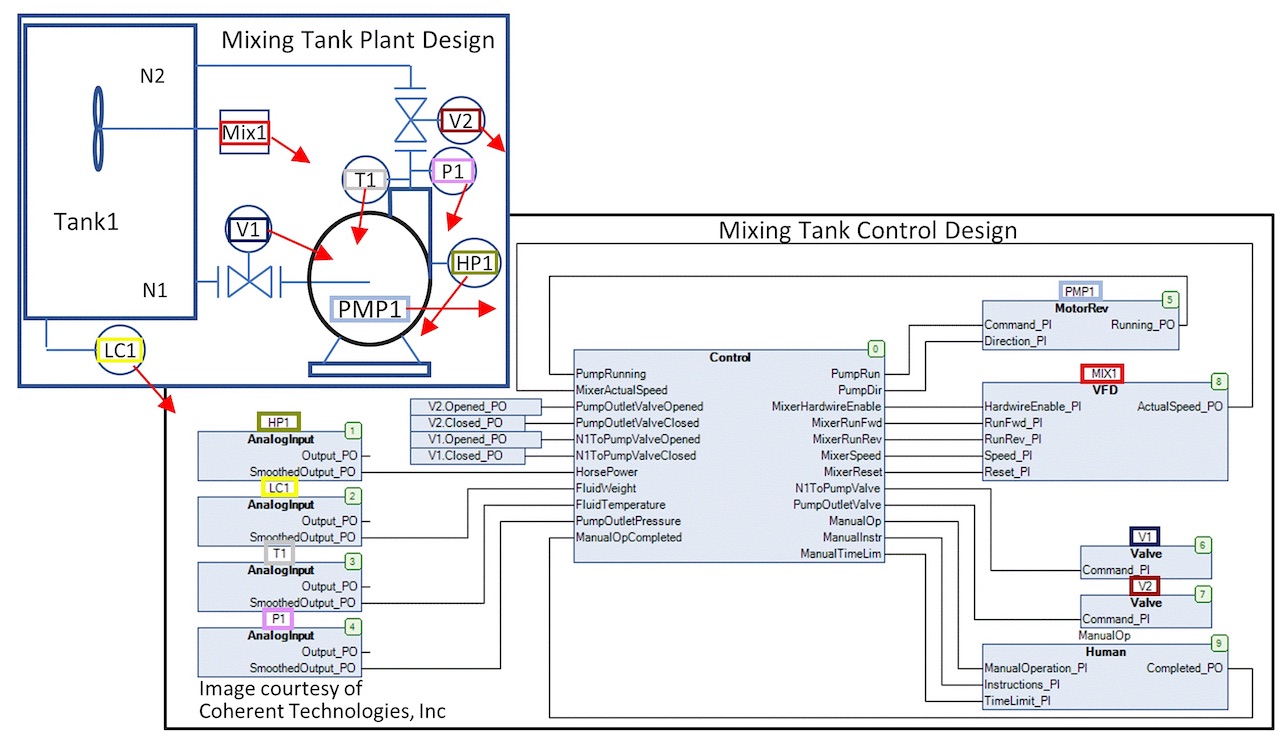
Objects for the controls can be designed to correspond to the objects in the plant in such a way that the control program begins to look very similar to the plant design as Figure 4 shows. With the right control diagram editor, the plant design and the control diagram could be the same.
To implement OOIP, controls engineers need to master two key OOP concepts: Encapsulation and instantiation.
Encapsulation
Encapsulation allows objects to be created that contain all the functionality and data necessary to control its matching plant object. The user does not need to know or understand the underlying implementation; they just use it. A good analogy is a car engine. The engine encapsulates pistons, valves, bearings, and many other objects and complex functionality. Drivers don’t need to know how an engine works; they only need to understand and interact with its interfaces: the starter and the accelerator pedal.
Figure 5: This analog input function block encapsulates analog input complexities including scaling, clamping, filtering, override, rate-of-change alarming, and high/low alarming. Courtesy: ControlSphere LLC[/caption]
Instantiation
Instantiation is the ability to declare and use multiple copies of an object without making copies of the object. In IEC 61131-3 programming languages, these objects are called “function blocks.” A function block is a data type in the same way an integer or a real number is a data type.
“Instances” of function blocks are created by declaring them in the same way instances of integers are declared. Behind the scenes, the compiler allocates unique memory for the variables in each instance of the function block in the same way it would allocate memory for an instance of an integer. Just like one can declare an unlimited number of integers (up to the memory capacity), one can declare an unlimited number of instances of a particular function block. Figure 6 shows how an object can be instantiated and used in the Codesys continuous function chart (CFC) editor. [Codesys Group manufactures Codesys, hardware-independent IEC 61131-3 automation software for developing and engineering controller applications.]
For example, as shown in figure 7, a particular make and model automobile is a vehicle “type” (in the same way an integer is a data “type”). No one can drive that make and model “type” until an instance of it is created (in exactly the same way an integer cannot be used until it is declared). The work order that instructs an automotive assembly line to create an instance of a certain make and model is analogous to the declaration that instructs the compiler to allocate integer memory. In this way, the make and model vehicle in the driveway becomes an instance of that data type.
While the user can declare (and the compiler can allocate memory for) numerous integers, the factory can manufacture numerous instances of a particular make and model vehicle “type.” In this way, a neighbor can have a particular make and model completely independent of the one created before. The functionality is encapsulated in each instance of the object (potential quantum entanglement notwithstanding).
Abstraction, nesting, interfaces
The use of encapsulation and instantiation leads to the use of three other OOP concepts. The first is abstraction, which is where detail is grouped by level in a hierarchy so the programmer only needs to deal with the relevant level of complexity at any one level of the design. The second is nesting, which allows objects to instantiate other objects. The third is interfaces, which provide a simplified means of interacting with the next level in the hierarchy.
In the automotive analogy, the vehicle has an engine, which has a starter, which has an armature, which has copper wire, which is mined and refined at certain locations. Abstraction can leave the nested complexity of the engine and the mining of its copper to others where that level of detail is appropriate for that level in the hierarchy. The user only needs to know the interfaces to engine – the starter and the accelerator pedal.
OOIP uses the same concepts as Figure 8 shows. At the top level, a plant object can nest (instantiate) two reactor objects, each of which have abstracted away the complexity of two auger objects, each of which has nested motor and shaft encoder objects. The motor object contains all the functionality required to control that motor (close its contactor, monitor its auxiliary contact or centripetal switch to verify it started, generate alarms if it doesn’t start, etc.)
Thanks to abstraction, the only concerns at any level of the hierarchy are the interfaces to the next level. For instance, the auger will have an input interface to turn the motor on and an output interface to feed back the pulses from the shaft encoder. At the reactor level, there is no need to know or deal with any of the underlying complexity such as starting the motor or generating alarms.
An exception is if there is a need to know if the motor has started, which would be the case if the auger had redundant motors. However, in that scenario, the additional functionality would be abstracted away into an additional layer of hierarchy. Instead of the auger instantiating a motor, it would instantiate a redundant motor, which would instantiate multiple motors itself and the logic to start a spare motor if the primary motor fails. The interface to the auger would still only be the command to run the motor. Each level encapsulates all the functionality it can and only looks to higher levels for tasks it cannot do itself.
Object configuration, I/O mapping
The difference between task-based control and object-based control can be compared to different forms of governments. Task-based control is analogous to a strong centralized government where new functionality must register with the Federal Bureau of Scaling, the Federal Bureau of Alarms, and so on. Object-based control is analogous to a decentralized government where new functionality is self-supporting and can largely take care of itself.
Now, you might be thinking, “Most would agree there is a need for some level of government” and “Not all make, model, and year vehicles are identical. They have different features and options. How are these handled in OOIP?” and “How does global I/O memory work with OOIP?” These are all very good questions. The first issue is addressed with central services, the second with configuration parameters, and the third with full-path I/O mapping.
To realize OOIP’s reusability benefit, I/O and parameters cannot be hard-coded into the instantiation of any object. For instance, in Figure 8, if the Speed_FO output of the motor object instantiated in the Auger1 object were tied to a global I/O variable, the Speed_FO of the motor in Auger2 would be connected to that same global. That auger object, therefore, could not be reused.
The same problem would occur if the motor configuration were hard-coded. For instance, say Auger1 has a smaller motor with a 1 Amp current alarm limit, and Auger2 has a larger motor with a 2 Amp alarm limit. If the 1 Amp parameter were hard-coded into the auger object, the 1 Amp limit would be locked into all instances. Again, that auger object could not be reused.
The I/O issue is resolved with full path mapping. This is a natural progression for the memory-mapping in the 1970s and the global symbolic mapping of the 1990s. A full path name is the dot-separated combination of the program name, followed by all the intervening instance names, and ending with the variable name (for instance: Main.R1.Auger1.AugerMotor.Speed_FO). Full path names are used to map the I/O to their appropriate process variables in the plant hierarchy as shown on the lower section of Figure 8.
The configuration issue is handled through a central service. On startup, instances of objects register themselves with a central configurator service. That service then obtains configuration data from a CSV file or an SQL database and distributes the values to each instance.
OOIP environment elements
Look for these capabilities to determine if a development system supports OOIP:
- A means to create self-contained control objects which correspond to matching plant objects and carryout all the functionality required for that plant object such as alarming, auditing, physical I/O, human-machine interface (HMI) I/O, scaling, control, etc.
- A graphical editor allowing an unlimited number of instances of objects to be declared, instances of objects to be interconnected in arbitrary fashions, and objects to instantiate other objects into a hierarchy of arbitrary depth and complexity. During runtime, the editor should allow for simple navigation of the hierarchy such as double-clicking on an instance of an object to descend into the project hierarchy and to navigate back.
- The ability to debug individual instances of objects during runtime, including: setting breakpoints within individual instances, single-stepping into individual instances, and viewing/changing the private variables of an instance of an object.
- A means for instances of the same objects to be differentiated by assigning unique values to the instance’s configuration inputs anywhere the instance may be in the project hierarchy. These configuration values should be sourced from a CSV/Excel file, SQL database, or via OPC UA. There also must be a way to search on the values of these configuration variables during runtime (for instance, to search on an ISA tag name configuration).
- The ability to map physical I/O to any variable in any instance anywhere in the project hierarchy (including mapping an input point to multiple instances). Composite I/O such as from a fieldbus device must be able to be mapped to individual variables, or to one or more data structure variables anywhere in the project hierarchy. The tool must provide a way to trace the path of a signal from its input, through the logic and to the outputs it drives (likewise in reverse from the physical output back through the logic to the physical inputs which influence that output).
- The capability to build hierarchical HMI objects that match the hierarchical control objects and the ability to interconnect the two objects (and their potentially thousands of underlying interconnections) via the top-level object’s instance name.
- The ability to print a “flattened” version of the hierarchical design showing the interconnections between the object instances and the unique configuration values on each instance.
- The ability to implement inheritance, methods, polymorphism, and interfaces can be helpful.
- An active user community and forum where open-source plant objects and advice can be shared.
Quickly leverage OOIP benefits
Tool vendors are beginning to make OOIP’s benefits available to controls engineers. To leverage those benefits, controls engineers need only master two key OOP concepts: encapsulation and instantiation. Controls engineers can encapsulate the plant object’s functionality into matching control objects and then instantiate those objects to create a control design that mirrors the plant design.
OOIP makes the design easy to build, easy to troubleshoot for plant technicians, and easy to maintain for future controls engineers. Just as the best of other general software advancements have been adopted for industrial controls, OOIP is following that same pattern and is becoming the future of control engineering.
Up next: part 2
Part 2 of this series shows how additional OOP techniques can be used to implement the centralized configuration service.
Gary L. Pratt, P.E., is president of ControlSphere LLC. Edited by Mark T. Hoske, content manager, Control Engineering, CFE Media, [email protected].
MORE ANSWERS
KEYWORDS: Control system programming, object oriented industrial programming
Object oriented industrial programming (OOIP) offers benefits.
Task-based control differs from object-based control.
Controls engineers only need to master two OOP concepts: encapsulation and instantiation.
CONSIDER THIS
Would code that’s easier to update and reuse make it worthwhile to learn?
ONLINE extras
More about the author: Pratt’s career began with Chevron corporate engineering in 1982 and has included numerous positions throughout the industrial controls industry. He holds patents in industrial controls and concentrates on sharing knowledge and experience with the next generation through consulting and training classes on IEC 61131-3 programming languages and Codesys integrated development environment (IDE).
For more elaborate examples of discrete, batch, and continuous control system designs implemented in OOIP, see this video.
A clearinghouse for open-source OOIP Functions Blocks and design examples can be found at www.OOIP-Foundation.org.
The Codesys IDE used for the examples in this article can be downloaded at no charge. The download includes a complete software-based PLC, which will run for 2 hours between resets.
For a video demonstration of OOIP, simulation, and configuring objects, see this video.
