Part 2: Plants and equipment are assembled from objects, and controls architecture should be too. Industrial programmers can realize the productivity of object-oriented programming (OOP) without the complexity by using object-oriented industrial programming (OOIP). See nine ways to determine if a development system supports OOIP.
Object-oriented industrial programming (OOIP) techniques deliver the productivity gains of object-oriented programming (OOP) while maintaining the ease-of-use and reliability required for industrial controls applications.
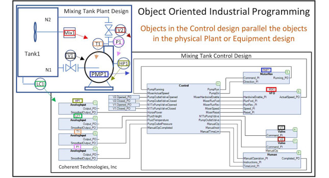
Part 1 of this series showed how OOIP can be used to build a plant or machine control program from a set of reusable components that mirrors the way a plant or machine is built from off-the-shelf components as shown in Figure 1.
Part 2 shows how blocks can build on other blocks to create large hierarchically partitioned systems and how to manage input/output (I/O) and configurations in an OOIP design.
Abstraction, nesting, and interfaces
In addition to encapsulation introduced in Part 1, abstraction, nesting, and interfaces are three additional concepts used in OOIP. Abstraction is where detail is grouped by level in a hierarchy so the programmer only needs to deal with the relevant level of complexity at any one level of the design. Nesting allows objects to instantiate other objects to build and logically partition large hierarchical systems. Interfaces provide a standardized means of interacting with the next level in the hierarchy. In the Mustang analogy from Part 1, the vehicle has an engine, which has a starter, which has an armature, which has copper wire, which is mined and refined at certain locations around the world as shown in Figure 2. Abstraction leaves the nested complexity of the engine and the mining of its copper to others where that level of detail is appropriate for that level in the hierarchy. The user only needs to know the interfaces to engine – the ignition switch and the accelerator pedal.
Figure 3 shows how abstraction, nesting, and interfaces can be used to build a hierarchical process plant. At the top level, the plant program can nest (instantiate) two reactor objects, each of which have abstracted away the complexity of two auger objects, which themselves have nested motor and shaft encoder objects. The shaft encoder and motor objects encapsulates all the functionality required to receive pulses from the shaft encoder and control the motor (such as close its contactor, monitor its auxiliary contact or centripetal switch to verify it started, generate alarms if it doesn’t start, jog, etc.)
Thanks to abstraction, the only concerns at any one level of the hierarchy are the interfaces to the next level. For instance, the variable speed motor in the auger has an interface to set the speed of the motor. At the auger level, users have no need to know or deal with any of the underlying complexity of the motor, such as determining if the motor is responding or generating alarms.
An exception is if there is a need to know if the motor is responding which would be the case if the auger had redundant motors. However, in that scenario, the additional functionality would be abstracted away into an additional layer of hierarchy. Instead of the auger instantiating a variable-speed motor (VSM), it would instantiate a redundant VSM which would instantiate multiple VSMs itself and the logic to use a spare motor if the primary motor fails. The interface to the redundant VSM would still only be the speed command. Each level encapsulates all the functionality it can and only looks to higher levels for tasks it cannot do itself.
Object configuration, I/O mapping
The difference between task-based control described in Part 1 and object-based control described in Part 2 can be compared to different forms of governments. Task-based control is analogous to a strong centralized government where new functionality must register with the Federal Bureau of Scaling, and the Federal Bureau of Alarms, and so on. Object-based control is analogous to a decentralized government where new functionality is self-supporting and can largely take care of itself.
Now, you might be thinking: “Most would agree there is a need for some level of government” and that “Not all Mustangs are identical. Mustangs have different features and options. How are these handled in OOIP?” and “How does global I/O memory work with OOIP?” These are good questions.
Figure 3: Abstraction, nesting, and interface concepts used to implement a process plant. Courtesy: ControlSphere LLC[/caption]
The configuration issue is handled through a central service. On startup, instances of objects register themselves with a central configurator service, and that service then obtains configuration data from a CSV file or an SQL database and distributes the values to each instance as shown in Figure 5. Configuration inputs simplify the design by allowing a small set of object types to meet the broadest possible set of needs. Part 3 of this series will show how additional OOP techniques are used to implement the centralized configuration service.
Nine OOIP environment elements
Look for nine capabilities to determine if a development system supports OOIP:
- A means to create self-contained control objects which correspond to matching plant objects and carryout all the functionality required for that plant object such as alarming, auditing, physical I/O, human-machine interface (HMI) I/O, scaling, control, etc.
- A graphical editor allowing an unlimited number of instances of objects to be declared, instances of objects to be interconnected in arbitrary fashions, and objects to instantiate other objects into a hierarchy of arbitrary depth and complexity. During runtime, the editor should allow for simple navigation of the hierarchy such as double-clicking on an instance of an object to descend into the project hierarchy and to navigate back.
- The ability to debug individual instances of objects during runtime, including: setting breakpoints within individual instances, single-stepping into individual instances, and viewing/changing the private variables of an instance of an object.
- A means for instances of the same objects to be differentiated by assigning unique values to the instance’s configuration inputs anywhere the instance may be in the project hierarchy. These configuration values should be sourced from a .CSV/Microsoft Excel file, SQL database, or OPC UA. There also must be a way to search on the values of these configuration variables during runtime (for instance, to search on an ISA tag name configuration).
- The ability to map physical I/O to any variable in any instance anywhere in the project hierarchy (including mapping an input point to multiple instances). Composite I/O such as from a fieldbus device must be able to be mapped to individual variables, or to one or more data structure variables anywhere in the project hierarchy. The tool must provide a way to trace the path of a signal from its input, through the logic and to the outputs it drives (likewise in reverse from the physical output back through the logic to the physical inputs which influence that output).
- The capability to build hierarchical HMI objects that match the hierarchical control objects and the ability to interconnect the two objects (and their potentially thousands of underlying interconnections) via the top-level object’s instance name.
- The ability to print a “flattened” version of the hierarchical design showing the interconnections between the object instances and the unique configuration values on each instance.
- The ability to implement inheritance, methods, polymorphism and interfaces can be helpful.
- An active user community and forum where open-source plant objects and advice can be shared.
Up next: part 3
Part 3 of this series describes the power of IEC 61131-3 “Interfaces” and show how this feature allows distributed objects to register with a central service, and show how to implement central services. Examples will include a central configuration service which allows the configuration inputs for objects distributed throughout the plant to be written to or read from a centralized CSV or SQL database, a central storage service which allows tuning parameters to be gathered from distributed objects and backed-up in case of hardware failure, and a centralized alarm service which allows objects to deal with their own alarms and coordinate through a central service.
Why use OOIP, digitalization
In addition to encapsulation and instantiation discussed in Part 1 of this series, the concepts of abstraction, interfaces, and nesting further promote reusability of objects and simplification of control system design. In addition, full path mapping and centralized configuration services are critical enablers of reusable objects. In total, these features of OOIP allow the control system design to be built from objects in the same way the plant or equipment is built from objects so the physical and control designs could become one in the same. The digital matches the physical in an understandable way. Perhaps in the future, equipment suppliers will provide these control objects for their equipment.
Not only does OOIP make the design easy to build, it makes the design easy to troubleshoot for plant technicians and easy to maintain for future controls engineers. Just as the best of other general software advancements have been adopted into the industrial controls world, OOIP is following that same pattern. OOIP is the future of controls engineering.
Part 3 of this series discusses OOIP interfaces and methods.
Gary L. Pratt, P.E., is president of ControlSphere LLC. Edited by Mark T. Hoske, content manager, Control Engineering, CFE Media, [email protected].
MORE ANSWERS
KEYWORDS: Control system programming, object oriented industrial programming, OOIP
Object-oriented industrial programming (OOIP) offers benefits beyond OOP.
OOIP capabilities include ability to create self-contained control objects matching real-world objects.
Part 3 looks at IEC 61131-3 interfaces.
CONSIDER THIS
Are you supporting digital designs with OOIP, matching objects to real-world components and systems?
ONLINE extras
More about the author: Pratt’s career began with Chevron corporate engineering in 1982 and has included numerous positions throughout the industrial controls industry. He holds patents in industrial controls and concentrates on sharing knowledge and experience with the next generation through IEC 61131-3 and CODESYS training and consulting.
A clearinghouse for open-source OOIP Function Blocks and design examples can be found at www.OOIP-Foundation.org.
The CODESYS IDE used for the examples in this article can be downloaded at no charge. The download includes a complete software-based PLC, which will run for 2 hours between resets.
For a video demonstration of OOIP, simulation, and configuring objects, see this video: www.controlsphere.pro/video/ooip.
For more elaborate examples of discrete, batch, and continuous control system designs implemented in OOIP, see this video: