Industrial rotary knives, usually servo-driven, cut a continuously-fed web into desired lengths. Software helps size and configure the servo for rotary knife applications.
Learning Objectives
- Rotary knife cycle requires careful servo sizing for effective motion control.
- When working on the rotary knife profile, consider acceleration and deceleration in the application.
- Next article looks at the servo sizing process for a single blade rotary knife./li>
Rotary knives are often used in industry to cut a continuously-fed web into desired lengths. Modern rotary knives are often servo-driven. Several controller manufacturers offer configurable software for controlling a rotary knife, but few offer a tool geared to sizing a servo for a given rotary knife application.
Sizing a servo for a rotary knife application can seem like a daunting task. However, there are a few basic principles that can help demystify the sizing process. This article focuses on understanding the fundamentals of a rotary knife application and the motion associated with the rotary knife cycle. A subsequent article will apply these principles to the rotary knife sizing process.
The rotary knife cycle, motion control
One aspect of the rotary knife that makes sizing difficult is the motion profile changes with the cut length. Understanding the rotary knife motion profile through the knife cycle is essential to the sizing process.
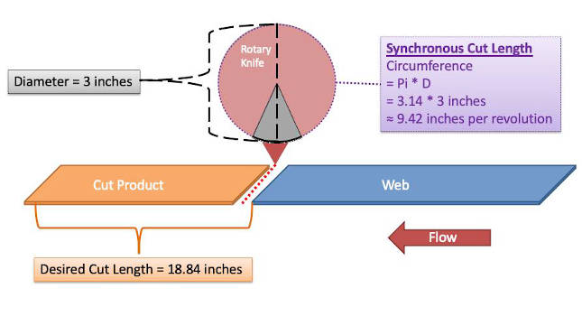
Looking at the rotary knife cycle in more detail, Figure 1 illustrates a simple diagram of a rotary knife system. Typically, the web moves at a constant velocity. The knife makes one complete rotation as the web travels a distance equal to the desired cut length. The cutting tip tangential velocity must closely match the web velocity while in contact with the web. Cutting takes place during this portion of the cycle. This article will refer to this portion of the cycle as the “working segment.” In some applications, it is desirable for the knife tip speed to be slightly greater than the web speed during the working segment, but for this discussion we’ll assume the tip speed is equal to the web speed.
While the tip is not in contact with the web, the knife axis must speed up or slow down to ensure it meets the web at the proper point to produce the desired cut length on the next cycle. The term “recovery segment” will be used when referring to this portion of the cycle.
The rotary knife velocity profile, synchronous cut length
If the knife were to run continuously at a velocity where the tip speed matched the web speed, the cut lengths would equal the circumference traced by the knife tip.
For this discussion, the term “synchronous cut length” will be used to refer to this cut length. Since there is no acceleration or deceleration during a cycle that produces a synchronous cut length, the torque required is the torque required to overcome system losses plus the torque required to cut the material. The “synchronous knife speed” to match the web speed is given by equation 1:
Equation 1) SKS = WS / (π * D)
Where: SKS = Synchronous Knife Speed in knife revolutions per time unit,
WS = Web Speed in distance units per time unit,
D = Knife Diameter in distance units
When using equation 1, be sure to use equivalent length units for web speed and knife diameter. For example, if web speed is given in ft/min and knife diameter is given in inches, convert the knife diameter to feet or the web speed to inches per minute before plugging into equation 1.
Acceleration: Cut length longer than synchronous cut length
If the desired cut length is longer than the synchronous cut length, the knife must slow down during the recovery segment, and then accelerate back to the required speed for the working segment. For cut lengths significantly greater than the synchronous cut length, the knife may even need to stop and dwell before accelerating to the required speed for the working segment.
Assuming an equal acceleration and deceleration rate, the worst case cut length based on torque requirements would occur when the motor must decelerate to zero speed and then accelerate back to web speed with no dwell. The term “critical long length” refers to this length. The critical long length occurs when the cut length equals the working segment length plus two times the recovery segment length. Any cut length longer than the critical cut length introduces a dwell period in the knife cycle. The dwell period increases as the cut length increases, which means root-mean-square (RMS) torque requirements decrease as the cut length increases beyond the critical long length. The equation for calculating the critical long length is given below:
Equation 2) LCL = ( p *D / 360) * (qW + 2*qR)
Where: LCL = Critical Long Length in distance units,
D = knife Diameter,
qW = working segment angle in degrees
qR = recovery segment angle in degrees
Deceleration: Cut length shorter than synchronous cut length
If the cut length is shorter than the synchronous cut length, the knife must speed up during the recovery segment and then decelerate to the speed required for the working segment. For a given web speed, as the cut length gets shorter, the knife has less web travel, therefore less time, to complete the entire recovery segment. So, the recovery segment velocity profile gets increasingly aggressive with decreasing cut length. The shortest desired cut length often dictates the knife servo sizing.
Figure 6: Velocity profile for cut length equals critical long length. The recovery segment can be viewed as a velocity profile superimposed on the synchronous knife speed. Courtesy: Yaskawa America Inc.[/caption]
Single blade rotary knife: Working segment, recovery segment
The single blade rotary knife cycle consists of a working segment and a recovery segment. During the working segment, the knife runs a speed at which the cutting tip speed matches the web velocity. For cut lengths not equal to synchronous cut length, the knife speed must vary during the recovery segment. Figures 6 and 7 demonstrate the recovery segment can be viewed as a velocity profile superimposed on the synchronous knife speed. This feature allows the user to simplify the sizing process to sizing for the worst-case velocity profile during the recovery segment.
The next article will apply this principle to the servo sizing process for a single blade rotary knife.
Sixto Moralez and Phil Drexler are regional motion engineers, Yaskawa America Inc. Edited by Mark T. Hoske, content manager, Control Engineering, CFE Media and Technology, [email protected].
KEYWORDS: Motion control, servo selection, servo programming
CONSIDER THIS
Are your servo-driven motion applications optimize with servo size and configuration?