An expert from ACS Motion Control describes six common methods.
By Cameron Sheikholeslami, ACS Motion Control for Control Engineering
Benjamin Franklin’s famous quote, "Time is money," is as true today as it was in the 18th century. Specifically, OEMs of modern manufacturing systems are driving to increase machine throughput while maintaining the lowest possible cost. Numerous automation providers offer many different solutions to this dilemma, and selecting which solution you should implement for your specific application can become a difficult decision.
This article will highlight the pros and cons of some of the most popular methods being advertised to increase throughput on preexisting machines including, optimal motion profile generation, special motion profiles that do not excite resonances, passive isolation systems, active isolations systems with feedback controller, active isolation systems with feedforward controller, and advanced disturbance rejection algorithms.
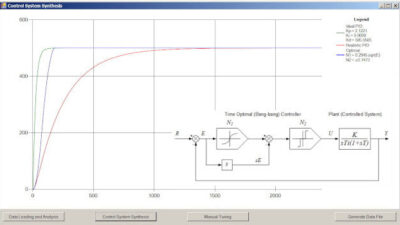
The first method that we will discuss to increase machine throughput is to determine an optimal motion profile . The most intuitive technique is to simply increase the motion velocity, acceleration, and jerk and thereby decrease the commanded move time. Although the acceleration and velocity have values that are limited by the drive current and voltage, it is usually not the best practice to exploit the maximum values. The two figures below demonstrate an extreme example, when a much shorter commanded move time leads to a longer total move time.
| |
| The left figure shows two different velocity profiles. The right figure shows the corresponding position errors. Source: ACS Motion Control |
The left figure shows two different velocity profiles for the same travel distance while the right figure shows the corresponding position errors. The reasoning behind this behavior is that decreasing the commanded move time will cause an increase in the settling time, with affects that are more pronounced when a higher resolution encoder is coupled with a tighter settling window. Since the total move time is equal to the commanded move time plus the settling time, this leads to the occurrence of an optimal commanded move beyond which any faster or slower commanded move will lead to a longer total move. The most common technique to determine this optimal commanded move is through a trial and error process. Unfortunately, even after finding the optimal commanded move, the desired throughput might not yet be obtained.
This leads to a different technique used to alter the motion profile to increase the throughput of the system – shaping the input to not excite resonances. All motion systems have resonant modes that are excited by specific frequency bands. These resonant modes are usually the cause of extended settling times that limit the throughput of the system. Simply stated, by shaping the motion profile not to include those frequency bands, the resonances will not be excited and the settling time will decrease. The process of shaping the motion profile is two-pronged; measure the resonant modes and then eliminate them from the motion profile. The simplest method to measure the resonant modes is to use the position error measured from the motor position sensor. By performing a Fourier Transform on the position error, the strongest resonant modes can be calculated. However, sometimes the resonant modes are invisible to the position sensor. In these circumstances an external sensor would have to be employed to measure the resonant frequencies. Eliminating the resonant modes from the motion profile is a slightly more difficult process, but patented methods exist that perform very well, even with low frequency resonances. The main disadvantages of shaping the commanded input is that it can only eliminate specific frequency resonant modes, it can slightly increase the commanded move time and the most common method to eliminate the resonances is patented and therefore costs money to use.
Another approach to increase machine throughput is accomplished by using isolation systems. In many situations, the motion system is located on the manufacturing floor and therefore in the presence of many external disturbances. These disturbances have a negative affect on the settling time and can be the limiting factor in increasing the machines throughput. Isolation systems work to decouple the motion system from disturbances that may enter from the floor and they come in two different packages, passive and active.
Passive isolation systems typically utilize a base mass supported on a soft spring. The spring can be made from different types of materials including air, metal and rubber. The spring works to minimize system vibrations above the resonance of the spring.For this reason, manufacturers of passive isolation systems tend to lower the resonant frequency of the spring to increase the effective isolation range. A result of the low frequency resonances is that the spring tends to be very soft, which can be detrimental for fast moving stages. Whenever a strong servo force is applied to the load, it also acts on the base and can cause low frequency vibrations. As the damping is very light in these frequency regions, the vibrations tend to last a long time. The figure below demonstrates this trend by comparing the position error of the stage when the isolated system vibrations are neglected, in blue, to one with isolated system vibrations included, in red.
| Position error with (red) and without (blue) isolation system vibration. Source: ACS Motion Control |
Active isolation systems exhibit this phenomenon to a much lesser extent. Active isolation systems exploit sensors that send signals to either feedback or feedforward controllers to counteract the vibration forces. Feedback active isolation systems work by measuring the vibrations affecting the isolated base and attempt to reduce them by using an actuator. This has an added benefit compared to passive isolation systems because feedback isolation systems absorb both the vibrational energy coming from the floor and the vibrations formed by the moving stage. However, complex tuning procedures are needed to correctly setup feedback controller in order to maintain high performance and stability. In addition, tuning readjustments need to be done periodically for these systems. Feedback isolation systems are also costly due to the need of additional sensors and digital controllers.
Feedforward active isolation systems are a much more cost-effective way of implementing an active isolation systems because they do not require any additional sensors. Feedforward isolation systems work by having a signal proportional to the applied force sent to the feedforward controller, which can then control an actuator to produce an opposing force. Since modern motion controllers generate the motion profile, a signal proportional to the acceleration can be sent to the feedforward controller. Assuming that the load does not change (or changes in a deterministic fashion) this signal will be proportional to the applied force. In many situations with multi-axial systems, positional information is also sent to the feedforward controller because of twisting. For example, lets assume we have an X-Y stage. If the Y-position is at its most negative position and an X-force is applied, a clockwise twist will occur. However, if the Y-position is at its most positive position and an X-force is applied, then a counterclockwise twist will occur. Additional benefits of the feedforward active isolation systems are that they cannot become unstable and the settling time improvement can be extremely substantial. However, similar to feedback active isolation systems, proper setup and adjustments need to be done to the feedforward gains in order to achieve optimal performance. Also, even with the optimal setup of isolation systems, the desired throughput might not yet be obtained.
The last method we shall discuss to increase system throughput is by applying advanced disturbance rejection algorithms . Most standard high performance motion controllers use a modified PID control algorithm, coupled with a low pass filter. For many applications these servo algorithms are more then sufficient to achieve high throughput and stability. However, situations can arise when a larger toolbox of control algorithms is necessary to improve the system throughput. Improvements to the servo control significantly help rejecting disturbances to the system.
The first tool we will discuss is the notch filter. The notch filter works by attenuating a specific frequency band. All motor-load systems have resonant frequencies located at a specific frequency band. These resonances limit the gain of the system since they will amplify any input signal with frequency components that lie within the resonant band. A notch filter can be used to attenuate the resonance and allow for a larger system gain that will increase the bandwidth of the system, which in turn leads to shorter settling times. However, phase lag will be induced prior to the notch frequency, and it will be followed by a phase lead. Care needs to be used when choosing the notch frequency, width and attenuation as negative affects can occur at other frequency locations.
Other specific filter types, such as lead and lag filters, can be used to modify the controller’s frequency response to yield larger system gains. However, the most useful tool is a Bi-Quad filter. The Bi-Quad filter is the most general form of a 2nd-order filter. It has two poles and two zeros, which gives it 4 degrees of freedom to shape the controllers frequency response. With practice, it is easy to shape the Bi-Quad filter to enhance the phase margin, gain margin, and most importantly, the bandwidth of the system.
The six methods discussed are some of the most common methods to increase machine throughput, but many other unique methods exist. Each of these methods discussed can be used successfully, however, the desired throughput still not might be achieved. In this case, a hybrid of multiple methods can be employed to optimize the machine throughput. Nevertheless, the absolute limit of machine throughput will always be limited by a machine’s mechanics. These methods can only be used to bring you closer to the mechanical throughput limit, but if the desired throughput is beyond the machine’s capabilities, then a different mechanical system will have to be used.
Cameron Sheikholeslami is a control and applications engineer at ACS Motion Control. ACS Motion Control’s SPiiPlus series of products includes a motion control simulator, integrated in the SPiiPlus software environment. The simulator makes it possible to develop multi-axis controller programs in a software-only PC environment by emulating theoretical motion with zero position (following) error and with I/O logic. It supports stand-alone application programming in ACSPL+, or Host-dependant application programming with C++, Visual Basic, and LabView. Download Version. 6.50 for free.
– Edited by Renee Robbins, senior editor
Control Engineering News Desk
Machine Control, Motion Control news from Control Engineering