To obtain optimal disposition of water injection flow in oil production facilities, linear programming techniques and advanced control based on fuzzy logic were applied. Better control increased field production and allows more effective responses to deviations that can damage people, goods or reduce production.

An advanced control strategy was developed for a water injection system composed of two storage pools, and two interconnected independent injection pads. A dynamic simulation model was created using chemical process simulation software, which allows the study of different situations in transient state and proves the feasibility of the control strategy, without developing a real test in the field.
The simulated model represents the complete injection system including the pumping units, flow lines and the interaction between facilities. Linear programming techniques (simplex method), and fuzzy logic were used to establish independent unconventional control strategies for the pools and injection pads, and general strategies to unify the system (pools-injection pads) to keep the produced – injected water mass balance stable. The model with the control system was analyzed for different operation cases and unwanted situations showing the process behavior and functionality of the strategy when compared with the historical data of the field.
Oil production, automatic controls
Water injection is considered worldwide as the most common method used and one that most contributes to the oil production as a secondary recovery technique. In Colombia, many of the oil fields use this method to expand oil production. The automation and control of the pumping systems is fundamental to regulate the water injection and efficiently increase oil production.
One facility available to perform the water injection in one of the production plants in Meta (Colombia), did not have an automatic control system that allows the stability of the facilities to avoid reaching operational alarm levels and generate an effective response in a preventive and corrective way.
This system has a facility to treat the production water, which is then pumped to the injection patterns PAD-3 and PAD-1. Common problems include loss of the pumping units that produce water for industrial uses, loss of the injection units in the two interconnected facilities (injection pads) and variations in the injected flow rate or amount of produced water.
To resolve the problem, an advanced engineering system was developed, including process engineering and advanced control strategies. Those involved built a dynamic model using the process simulator software that allowed observation of system behavior in a dynamic way and integrate it with the designed control strategy. The control scheme developed included an unconventional strategy based on fuzzy logic for each injection facility, where the suction and discharge pressures of the pump units interact simultaneously with the flow that passes through each.
An unconventional control strategy also was implemented to unify the injection system (production water treatment and injection facilities), which is focused on maintaining and achieving the mass balance that exists between the amount produced and injected, assigning the injection flow rate set point automatically in each facility.
This strategy allowed to provide greater autonomy, stability and operational continuity to the entire water injection system.
Methodology, process description
The production water treatment facility consists of two interconnected polish pools each with eight pumping units that transfer the water to the injection pads by means of three branches of 30 inches diameter. for each. In the pads there are multistage centrifugal pumps and internal combustion pumps that inject water into the wells. Figure 1 shows the diagram of disposal water process.
Due to the multiple interactions between the operative variables, this system is considered non-linear, and requires unconventional tools for modeling and defining the control strategies to be implemented.
Dynamic simulation
The dynamic simulation model of the water injection system was built in the chemical process simulator software. At an initial stage, the model was built in a steady state to ensure system stability. It was then moved to a dynamic state to represent the behavior of the real process and evaluate it against any perturbation. At this stage the fluid properties, initial operational conditions, the number of pumping units, the pipe diameters and lengths, and other accessories present in the system were established. The boundary conditions included such as pressure specifications in the inlet and outlet streams of the system, and the pumps were characterized with their respective curve. A loss of approximately 15% in efficiency was considered for the pool units.
Subsequently, the model was validated by simulating the specific field conditions and comparing with historical data, an average deviation of 5% was found. In general, the model behaves similar to the historical data, which indicates it can be used to analyze the behavior of the system. The results of the simulated scenarios are presented in Table 1.
Finally, the evaluation of different case studies was carried out. The behavior of the facilities was analyzed as if they were working on plant equipment. These studies led to the optimization of the control system through an appropriate control strategy for the process.
Control strategy injection system
The advanced control area rebuilt the control system installed in the facilities on programmable logic server emulators and developed a two-way communication interface that allowed real-time communication between the process simulator and the emulated control system. An emulation tool helped reproduce control logic developed for injection system operation.
Through the simulation was possible to determine the variables of interest behave in a nonlinear way, so a controlled based on fuzzy logic adapts better to the behavior of the system, since
it provides an inference mechanism that allows to simulate the procedures of the human reasoning in knowledge-based systems, it means that imitates the behavior of the operator in known situations accelerating or deaccelerating the pumps.
For the unification of the injection system (pools and pads), the mass balance was interpreted as a cost function and resolved through linear programming techniques, such as simplex, focused on maximizing the flow. The optimal flow set point that each facility must handle to maximize the injection was subject to these restrictions.
The simplex method is an iterative procedure that allows improvement of the objective function in each step. The process finishes when it is not possible to continue improving the value, meaning the optimal solution has been reached satisfying all restrictions.
Implementing advanced control strategies in the injection system is divided in two phases.
Phase 1: Integration of the injection system
This strategy sought to increase field production. For this, a variable that directly affects the production was selected, in this case, the injection flow rate. Consecutively, a mathematical function was found to describe the behavior of this variable subject to the constraints and elements of its system. Solving this function with a maximization as the target, the results finally show the optimal operating points to maximize flow–rate injection and improve oil production.
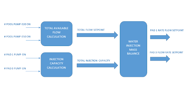
The cost function was focused in finding a mass balance between the produced water pumped from the pools and the injected water in each one of the pads. To determine this balance, the operational availability of the vertical pumps located in each pool is taken as a starting point. The total flow data must be distributed efficiently to each injection pads.
The distribution criteria depends on several factors:
- Number of available units turned on in eachpad
- Injection capacity of each units.
- Position of the valves that interconnect the branches to eachpad.
The function of the distribution algorithm is to find the optimal set point of flow rate, and automatically assign it to each of the diffuse control panels for injection flow, and accomplish the balance. To achieve this goal, it is necessary to account for the following conditions:
- The mass balance must be constantly verified through the flowmeters installed at the exit of the poolsandthe flowmeter installed at the interconnection point and at the inlet of each pad.
- If it is not possible to achieve the mass balance planned with the instantaneous conditions of the injection system, the control system will notify the operator to start or stop the pumping units in thepads.
- The control system should recalculate the flow set point, in case oftheloss of pumping units in the pads or in the injection pools, to determine the loss injection capacity and recalculate the new mass balance.
The control system for the integration of the injection system is presented in Figure 2.
Phase 2: Pad 3 control strategy design
This strategy sought to provide more stability and autonomy to the system to resolve disturbances that arise in the process, and are not possible to mitigate effectively and on time through manual operation.
The proposed control strategy brings a dynamic equilibrium among the three variables that interact in the injection system (flow, suction pressure and discharge pressure).
Tuning the only conventional control loop was not possible due to the strong non-linearity of the model (proved through the dynamic process model), and in turn, it did not consider changes in the suction and discharge pressure. Therefore, a controller based on fuzzy logic better adapts to the behavior of the system.
However, the conceptual development of one fuzzy logic controller becomes too complex and with high computational demand.
For these reasons, it was decided to design a diffuse controller for each variable that interacts with the pumps. The only control element that could be used was the governor that modifies the combustion motor velocity. It was necessary to choose a unique control output to the speed governor. Following the same scheme of the fuzzy controller, the final output is determined according to the dynamic behavior of the change of the output of each one of the fuzzy controllers in time.
The fuzzy logic controller is composed of a block responsible for receiving the percentage error of the process variable with respect to the set point (the percentage is obtained from the range of the process variable). From this percentage error, a variation of the error is estimated an identified as “DeltaError.” The general scheme of the fuzzy logic controller is shown in the Figure 4.
The fuzzy control block
The basic scheme for all loops of all “fuzzy control” blocks was taken from Figure 4. In this case it is proposed to have as error variables of entrance
e(k)=PV(k)SP(k)
and the delta error
Δe(k)=e(k)-e(k-1)
of the process variable. This scheme is taken to the fuzzy designer tool, where there are two fuzzy input sets, the first for the error, and the second for the delta of the error.
Results: Imitate expert behavior
The idea is to imitate the behavior of an expert through the interaction of fuzzy inlet sets. In this case, the goal is to imitate the operator´s expertise by reproducing the action taken when deviations in the variable of interest are detected. To reproduce this knowledge, some rules are created to evaluate the interactions of the linguistic values of each of the fuzzy sets and associated them with the output.
A series of operations are carried out on this diffuse set of outputs that will allow obtaining a unique value of controlled variable by each control panel. These in turn will be evaluated to determine which of the three will be applied to the speed governor.
The decision made for the controller is based on the experience of the operator, and some set of rules are established where this heuristic is established. Partial results can be seen in Table 2.
In the event of a shutdown of a PAD1 unit, the flow rate set point is recalculated and assigns the lost flow to the set point of PAD2. In this way, the same injection rate is maintained despite the loss of the pumping unit.
Maintaining the active distribution strategy, an increased in injected flow was seen, which leads to an increase in the barrels of oil recovered. A comparison between data before the control strategy and after the injection control is presented in Table 3.
Table 3: Increased injection flow: The control strategies developed were first tested on a dynamic simulation performed in the Aspen Hysys V10 software, to evaluate the dynamic behavior of the system and the common disturbances that can affect its normal operation.
Courtesy: Proctek SAS
Process simulator benefits
An advanced engineering system was developed integrating process engineering and advanced control strategies to optimize the water injection flow in oil production facility. Linear programming techniques such as simplex and a control based in fuzzy logic were used since the system presents non-linearity. The control strategies developed were initially tested on a dynamic simulation performed in the chemical process simulation software, to evaluate dynamic system behavior and the common disturbances that can affect normal operation.
Using process simulators shows several benefits by allowing optimization of several systems and process plants. This is due to changes in the model, which allows different scenarios to be evaluated without field tests that may require long periods of time and extensive resources.
The proposed strategies allowed control of the total injection flow, increasing field production. In addition, an effective response was generated on time when deviations are detected in the process that can cause damage to people, loss of goods or reduction in production.
Juan David Medina Gonzalez, Silvia Marina Araujo Daza MSc, and Hernan Ivan Cadena Celis are with Proctek S.A.S. Edited by Mark T. Hoske, content manager, Control Engineering, CFE Media, [email protected].
KEYWORDS: process control, process simulation
A dynamic simulation model was created using chemical process simulation software without developing a real test in the field.
This was done using linear programming techniques and advanced control based on fuzzy logic.
Using process simulators shows several benefits by allowing optimization of several systems and process plants.
CONSIDER THIS
How could linear programming and fuzzing logic help your advanced control applications?
ONLINE
If reading from the digital edition, click on the headline for more resources. www.controleng.com/magazine
Learn more about Proctek SAS in the Global System Integrator Database.


