How to integrate control system design for wind turbines with blade-pitch and power-electronic control. Optimize parameter-tuning for different electromechanical control functions. See 10 related graphics.
Type III and Type IV wind turbines are complex engineering systems that require a combination of blade-pitch and power-electronic control systems to achieve more efficient and reliable performance. Designing a complete control system for wind turbines bears considerable complexity in the multidomain control architecture and the selection of parameter settings in each control loop.
Applying optimization techniques to detailed simulation models can automatically update parameter settings in the integrated control system and maximize the electromechanical turbine performance for a given control function and over a given operating envelope. Auxiliary control signals can be used in the power converters to mitigate subsynchronous resonance. Parallel computing can be used as a means to run a large number of simulations in a more time-efficient manner and to more efficiently measure the confidence bounds associated with the control system operation.
Multiple control loops
Control architectures that contain multiple, coupled loops have long been a challenge for control engineers, particularly from the perspective of selecting appropriate parameters to achieve the desired response. This challenge is compounded when the control loops act across different physical phenomena, such as mechanical control of blade pitch and electromagnetic control of shaft speed, where a control engineer may not have domain experience that spans the multiple physical properties of the complete system.
Nevertheless, a control engineer’s skills and instincts are irreplaceable for complex control design, regardless of the physics of the system being controlled. Also, parameter settings achieved through manual tuning are certainly a more efficient way to get into the ballpark of the desired response. This is Pareto’s Principle in action, where 20% of the work gets you 80% of the way to the desired response. The fine-tuning stage is particularly time consuming, and this is where the incremental improvements in response are made that provide further performance benefit. Numerous benefits of fine-tuning include improved power quality, reduced mechanical fatigue, and precise response to system operator commands. Computer simulation and automated parameter tuning are a compelling addition to a control engineer’s workflow in this regard. The primary benefit comes when the final effort to achieve maximum response is transferred from an engineer to an automated optimization and test environment.
Through consideration of Type III and Type IV wind turbines, there are optimization methods to supplement a parameter-tuning task for different electromechanical control functions. The following functions are considered: entry-into and exit-from power limiting at higher wind speeds, reactive power support during low-voltage conditions, and mitigation of subsynchronous resonance as a local control function of the wind turbine.
Power limiting
A turbine’s ability to limit power effectively is a control strategy that requires consideration of multiple wind speed scenarios to test the robustness of the ability to enter into a limiting condition, and then the ability to smoothly transition out of a limiting condition.
Two mechanisms are at work in the power-limiting function in both Type III and Type IV wind turbines. First, an electromagnetic torque reference is sent to the power converter (rotor side converter for Type III and generator converter for Type IV) to regulate rotor speed to its rated value. This reference will most likely saturate in the power-limiting condition. Second, blade pitch control actuates the blades out of the wind to attempt to limit power to the rating of the generator. Blade pitch actuation may or may not saturate depending on the severity of the wind, but we consider only the scenario where blade pitch authority is maintained. The control challenge is to ensure the blade pitch reference and electromagnetic torque reference effectively limit power and do not cause unnecessary transients in the exit from a power limiting condition.
For example, consider the scenario of testing the power-limiting capability of a Type III wind turbine on three stylized wind profiles shown in Figure 1. The Type III wind turbine has parameter settings on the blade pitch and electromagnetic torque feedback control systems, causing the turbine to exhibit an active power response shown in Figure 2. While the turbine enters into an acceptable power-limiting condition for each wind profile, the exit from the limiting condition is rather poor. It lacks symmetry, because the power ramp-down during wind speed reduction does not mirror the power ramp-up during wind speed increase, and the transients during power reduction detrimentally impact power quality.
To improve system response you can create an optimization task that aims to provide an improved fit to the desired symmetry and reduce the transient effect. You can also define response bounds in which the symmetry is specified with a desired level of confidence, such as the bound shown in Figure 3. The responses shown in Figure 3 illustrate the progression of the optimization task. The optimization focuses on selecting parameters of the electromagnetic torque and blade-pitch control feedback control systems in order to minimize the error between simulated response and the desired bounds. Figure 4 shows the outcome of the optimization, where control parameters were automatically selected to provide an improved fit of active power within the desired bounds for the three separate wind profiles.
Reactive power support
In a post-fault condition, Type III and Type IV wind turbines might be required to provide reactive power support to aid voltage recovery. Since wind turbine power converters share their capacity between the flow of active and reactive power, the reduction of active power flow in a post-fault condition will increase the reactive power capacity available for voltage recovery.
Figure 5 shows the voltage response of a Type IV wind turbine with and without a control function to increase reactive-power capacity during low-voltage conditions. In this example, the control function is to reduce active power output through blade pitch actuation, to increase reactive power capacity in the power converters. In addition, the electromagnetic torque holds shaft speed constant during the period of reactive power support. Once the period of reactive power support is over, blade pitch control brings active power back to a nominal level. The turbine with increased reactive-power capacity can better respond to the support of voltage.
After the reactive power support period ends, the wind turbine can revert to full active-power control and recover its active power output to nominal levels. There is clearly a premium on not only effectively supporting low-voltage recovery, but in quickly establishing nominal power levels in the post–low-voltage condition. Automated parameter tuning may be used to select control gains that will achieve a specified performance bound. Figure 6 shows an example of an optimization task that reduces and recovers active power during and after a period of reactive power support. The overlaid responses show the progression of the optimization.
Mitigate subsynchronous resonance
Subsynchronous resonance (SSR) occurs at frequencies below system frequency and is generally caused by an interaction between series capacitance on the grid and torsional modes of a turbine shaft.
Both Type III and Type IV wind turbines offer the opportunity to tackle SSR locally at the turbine, although the mechanism for SSR mitigation is different for each technology.
With a Type III wind turbine, there is a direct electromechanical interaction between rotor shaft torsional modes and series capacitance on the grid. The torque at the rotor must therefore be actively controlled to mitigate an SSR response with local control.
Computer simulation can explore different architecture options to determine the feasibility of a given control function. In the example shown, a stylized torsional mode is modeled using a two-mass model on the turbine shaft that will interact with a series capacitor on the grid. The control architecture considered is an auxiliary feedback signal that aims to provide damping to electromagnetic torque through the rotor side converter.
Figure 7 shows an example of the use of auxiliary damping in the rotor side converter for SSR mitigation in a Type III wind turbine. In this case, blade pitch control is not considered, because the SSR frequency is beyond the bandwidth of the blade pitch actuators.
With a Type IV wind turbine, the dc link between the grid converter and the generator converter naturally reduces the interaction between the torsional modes of the shaft and series capacitance on the grid, thus minimizing the SSR effect through passive means. The size of the dc capacitor will influence the amount of interaction that exists: the larger the dc capacitor, the less the interaction. If the dc capacitor sizing is such that an objectionable level of SSR still exists, consider an auxiliary signal control strategy similar to that described in the Type III discussion.
Figure 8 shows the impact of dc capacitor value on torsional oscillation for an example Type IV configuration connected to a series-compensated transmission line. A fault is applied at 8 secs and then cleared one cycle later, causing torque amplification to occur. As expected, an increase in dc capacitor value results in a decrease in torque amplitude following fault clearance.
Monte-Carlo simulation
After selecting control parameters for each control function, a Monte-Carlo test can determine confidence bounds of the effectiveness of system operation through a large number of operational scenarios. This stage provides further information on the control functions and may lead to further design improvements.
For example, Monte-Carlo testing can indicate unacceptable behavior in a number of operational scenarios not considered in the original design framework. You can incorporate these cases into the optimization task to improve the response in those conditions.
Figure 9 shows a histogram of wind turbine power output for 12 wind profiles of 5000 sec duration. Responses are shown for an original control system and also an automatically tuned control system, described in the Power Limiting section.
The plot in Figure 9 shows that the tuned controller is more effective at limiting power closer to the machine rating.
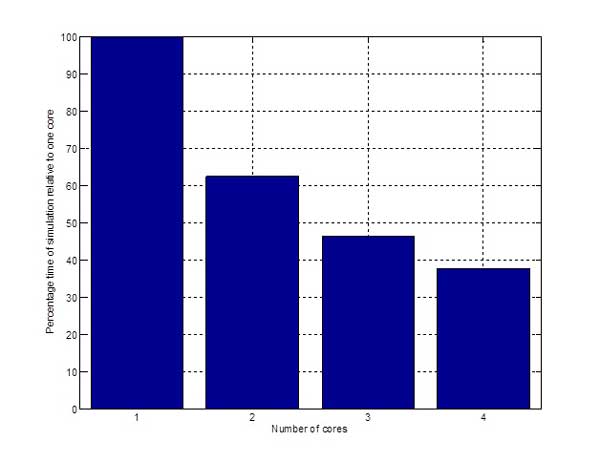
To enhance Monte-Carlo testing, parallel computing can speed up the execution of multiple simulations. Figure 10 shows the acceleration in running 12 simulations of 5000s duration over one to four processors. You can gain further speed advantages by distributing the multiple simulation runs over a larger number of processors in a computing cluster.
Optimization
Monte-Carlo simulations run across multiple processors offer additional benefits by providing a statistical measure on the effectiveness of a control function, thus allowing you to more clearly understand the risk associated with running a specific control function.
– Graham Dudgeon, PhD, is energy production industry manager, MathWorks; edited by Mark T. Hoske, content manager CFE Media, Control Engineering, Plant Engineering, and Consulting-Specifying Engineer, [email protected].
https://www.controleng.com/tutorials