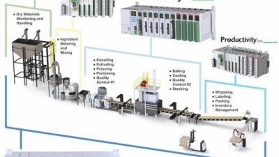
After the supervisory control and data acquisition (SCADA) software is in place and the system is optimized, system information flows from sensors, field instruments, and other process tools to the control room and back again. Users must provide automatic and manual control commands to alter the process.
To understand the return of supervisory control and data acquisition (SCADA) to the field, the journey begins at the programmable logic controller (PLC). Reasons for looking at the PLC will become apparent by considering an example of a transmitter measuring a tank’s temperature and a solenoid valve opening to allow steam to pass through a heating coil in the tank to heat its contents. In the example, PLC logic (not the SCADA) controls the solenoid valve.
PLC control logic
Consider that the process operations department is asking for the tank’s temperature to be controlled at 75°C (167°F) with a process temperature variation between 70°C (158°F) and 80°C (176°F). The control is designed according to these parameters:
- When tank temperature drops below 72°C (161.6°F), turn "ON" the solenoid valve.
- When tank temperature rises above 78°C (172.4°F), turn "OFF" the solenoid valve.
Having documented the control parameters, they can be translated into a single-rung ladder diagram (see Figure 1).
The next step is to run a simulation which works as expected. The logic seems to be air-tight. But now consider, how will the SCADA interface with and/or interrupt this air-tight logic? Stay tuned.
Preparing the PLC program
The PLC program must be prepared to receive SCADA commands. The first step is to define and document the operator’s involvement with the valve. The operator must:
- Observe the valve status
- Have program access to change the valve’s control mode-automatically with the logic or manually from the SCADA screen
- Have the capability of issuing a manual command to open or close the valve from the SCADA screen.
The second step is to allocate a location in the PLC memory for each function so that when the SCADA wants to do these functions, it has to only write (or read) information to (or from) these locations. In this case, three memory bits (or internal relays or markers-the name highly depends on the PLC vendor’s manual, but they are all the same) will be allocated. Bits and not words were chosen because these are discrete commands and information. Allocate memory locations as follows:
- For valve status, allocate M10
- For AUTO selection, allocate M11
- For Manual Command, allocate M12.
Now it’s time to modify the PLC program (see Figure 2).
Now the updated PLC program is ready to receive SCADA commands. It’s also time to add these new variables to the OPC server. Note that in actual applications, users mostly rely on an external feedback signal to indicate the actual valve status in the field. It is not advisable to use only the PLC output because in doing so, there could be an unknown actuator failure. This is done here only to simplify the subject.
Modify the OPC server
Referring to the steps performed in the article, "Journey to the center of the plant: SCADA systems information flow," open the ABC OPC server and modify the configuration file by adding three more OPC items to the same OPC Group "TANK." The configuration should look like the one in Figure 3. The PLC’s OPC server software can be used to test the required functionality by writing 1s or 0s into these memory bits. After operation is verified, modify the XYZ SCADA software.
Update the SCADA
Back to the SCADA software, first create three new tags in the "Tags Database" for three new variables:
- Valve_Status
- Valve_Auto
- Valve_Manual_Command.
Next, go to the graphics editor, open the "Tank" screen, add a valve symbol, set the data source property to the "Valve_Status" tag, and click "save." Now there is a valve symbol that is changing according to the actual solenoid valve status.
Add a couple of toggle switch symbols to the screen-one for the mode selection and one for the manual command. Link them to the tags, and this is a fully functioning system (see Figure 4).
Run the SCADA, test everything live, and it works like a charm.
What? The valve is not operating? No? Why?
Let me have a look … oh, here you go, you forgot to connect the solenoid valve to the PLC output, wait let me see…
The solenoid valve nameplate says it operates at 220 V ac, and the PLC output module is a transistor type that can only handle up to 24 V dc. This should have been planned from the beginning. But don’t worry. If there is a will, there is a way. This time the way is called the interface relay.
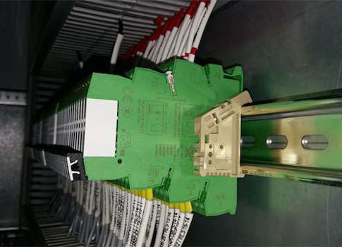
The interface relay
The interface relay is also sometimes called the interposing relay. Now, an interface relay must be installed in the PLC panel. It provides isolation between the PLC output and the solenoid valve, allowing the PLC to operate the relay coil with 24 V dc, and the relay contact will connect the 220 V ac supply to the solenoid valve.
As with normal relays, interface relays have two parts (see Figure 5). The relay base (or socket) provides the connections to the coil and contacts of the relay and an easy way to plug and unplug the device. The actual relay contains the coil and contacts, which provide the switching function needed.
With the interface relay installed, the solenoid can be controlled using the PLC output Q1. The SCADA application is fully functional.
Shady Yehia is the founder and author of The Control Blog and is the instrumentation, control, and automation proposals and engineering manager in a process technology integration company based in Qatar and operating in the EMEA region. The Control Blog is a CFE Media content partner. Edited by Jack Smith, content manager, CFE Media, Control Engineering, [email protected].
Key concepts
- To understand the SCADA return to the field, the journey begins in the middle at the programmable logic controller.
- It is not advisable to use only the PLC output because in doing so, there could be an unknown actuator failure.
- The interface relay is also sometimes called the interposing relay.
Consider this
Ensure all of the planning is done before you embark on the project.