Control of a self-limiting process with a proportional-integral-derivative (PID) controller begins with learning the role of controller gain, integral and derivative in controlling the self-limiting process. Controller gain responds to the present, integral corrects based on the past, and derivative can be used to best-guess the future.
Learning Objectives
- Learn how PID controller gain, integral and derivative interact with a self-limiting process and the roles each play in creating a functional controller.
- Understand visual cues that alert the control professional to when too much gain, integral, or derivative is being used.
PID control of a self-limiting process insights
- Controller gain alone cannot eliminate error. Raising controller gain does lower the error, but raising controller gain too high will cause instability (swinging). When swinging the PV and OP peaks will line up.
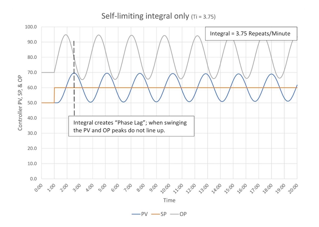
- Integral will eliminate error, however too much integral will cause instability (swinging). When swinging the PV and OP peaks do not line up.
- Derivative works with controller gain in response to process disturbances, providing stronger control. Derivative works the opposite direction of controller gain when the SP is changed, restraining controller response to SP changes. Too much derivative will cause instability.
Before controlling a self-limiting process with a proportional-integral-derivative (PID) controller start by learning the role of controller gain, integral and derivative in controlling the self-limiting process. Controller gain responds immediately to changes in error (the present), integral eliminates error (corrects based on the past), and derivative can be used to guide response based on the direction the PV is going (best guess of the future).
In PID spotlight part 3, I stated that “how we tune a PID controller depends on the type of process response.” In other words, once you mate a PID controller to a process the mated pair behave in a way that is unique to that (type of) process. Furthermore, a PID/self-regulating process behaves, and is therefore tuned, differently than a PID/integrating process. There are different things to look for and a different set of rules.
This and the next several installments in this series explain how to tune self-limiting processes. We started with self-limiting processes because they are the most common.
For each type of process we will explore how controller gain, integral and derivative individually affect the process, beginning with controller gain. We do this to understand how each function of the PID controller works individually so that we can then understand how to blend them to get a functioning PID controller.
Gain (Proportional) interaction with a self-limiting process
Figure 1 illustrates how controller gain alone interacts with a self-limiting process.
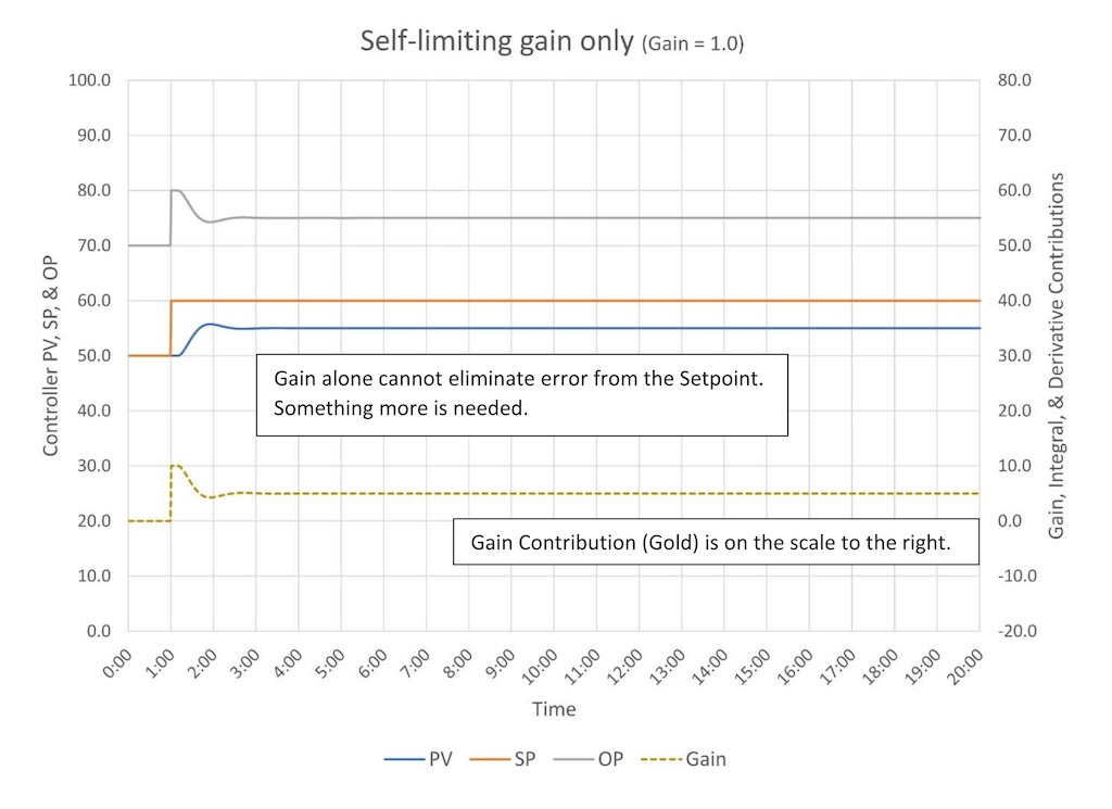
As we saw in PID spotlight, part 2, a controller gain of 1 causes the controller OP to change 10% when the SP is changed 10%. However, now that we’ve connected the PID controller to a self-limiting process, the PV responds to the change in valve position (we hope, otherwise we have a problem.) When the PV starts to respond the error drops, the controller gain contribution falls with it, and the valve moves. Eventually the PV ends up closer to the SP, but it never gets to the SP.
We can change how close the PV gets to the SP by increasing the controller gain as in Figure 2. The controller gain is now 2.5 and the PV is closer to the SP after the controller lines out.
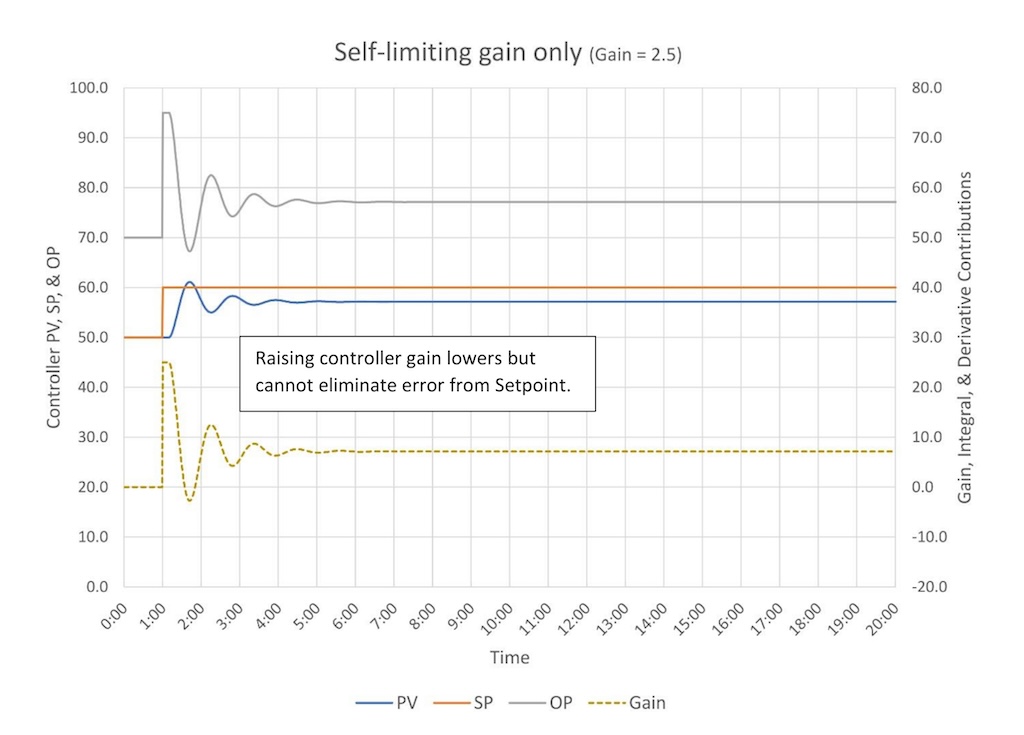
Unfortunately, as we raise the controller gain the controller starts to swing, and if we raise the controller gain high enough the controller will go unstable (Figure 3 – the controller is unstable at a controller gain of 4.3).
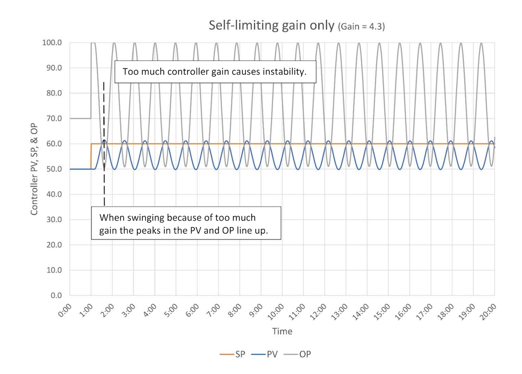
Notice that if too much controller gain is causing the controller to swing, then the peaks in the PV and OP line up. We will use this as a visual cue that we have a control tuning problem when we talk about heuristic tuning methods. Also note that the PV for the most part stays below the SP; no matter how high the Controller gain goes you cannot eliminate the error between the PV and the SP.
Finally, the takeaway from all this is controller gain alone cannot eliminate offset from setpoint (error). Something more is needed.
Integral (Reset) and self-limiting process
Figure 4 illustrates how integral alone interacts with a self-limiting process.

In Figure 4 the SP was increased 10% at the 1-minute mark. The controller keeps resetting the output until the error is zero. Because integral keeps working in one direction until the error is reduced to zero it will cause overshoot; it goes too far. Once it shoots past the SP it turns itself around, and, depending on how aggressively it is tuned, it will overshoot again (and again and again….)
To avoid overshoot and the cycling that comes with it, the integral action can be slowed down (Figure 5). If we slow down the integral action enough, we will stop it from cycling. But it will take longer to get to setpoint, and the goal is to try to get to SP as quickly as possible.
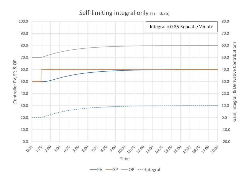
Another thing I want to point out in Figure 6 is integral action causes what the frequency response analysts call “phase lag.” What this means is as we add integral action, we run the risk of delaying the controller response enough to create positive feedback, which will cause the controller to go unstable. Notice how the peaks of the PV and OP swings do not line up; this is caused by the delay that adding integral to a controller naturally creates (the controller is too focused on the past and not on the present). Up above we saw that when too much controller gain causes swinging the PV and OP peaks line up. This difference from how integral behaves gives us a quick visual cue that tells us if a controller has too much controller gain or too much integral.
Derivative (Pre-act) interaction with a self-limiting process
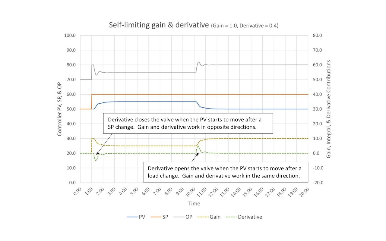
Figure 7 illustrates how derivative interacts with a self-limiting process.
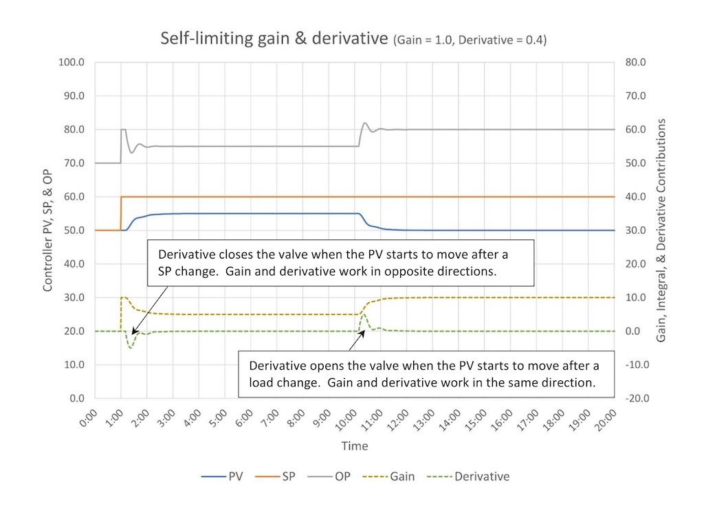
Derivative in most PID implementations should act on changes in the PV, not the error. Its purpose is to give the controller an extra kick when it sees the PV change direction.
Figure 7 shows how a gain plus derivative controller responds to a SP change and a disturbance (load change). After a SP change (1 minute) we see the controller gain contribution (and OP) step up 10%. When the PV starts moving two things happen; the controller gain contribution drops as the error drops and the derivative contribution goes negative – it pulls back – which causes the controller OP to close faster than it would have just on controller gain. This will slow down the rise of the PV. The controller gain and derivative work in opposite directions after a SP change.
At the 10-minute mark, a disturbance comes through. The controller gain and derivative respond in the same direction to counteract the disturbance. Controller gain and derivative work together to move the OP faster and farther than gain alone would have, which helps to limit the overall size of the disturbance.
Because derivative works against controller gain on a SP change, but with controller gain on a load disturbance, derivative allows us to use a higher controller gain because it will tend to limit overshoot on SP changes and still allow aggressive tuning which will limit how long a disturbance will upset the process.
Note that derivative does not eliminate offset.
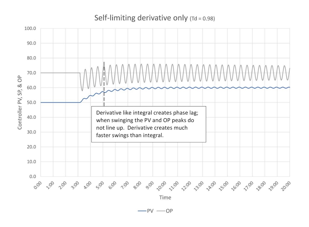
Figure 8 shows that, like controller gain and integral, too much derivative causes instability. Derivative, if it is used, should be used lightly, therefore, you should never run into a controller that is swinging solely because it has too much derivative. That said, if a swinging controller has derivative remove it before addressing other tuning issues. It may be added back later after all other tuning issues are fixed.
Summary: Blending gain, integral and derivative?
Good control-loop tuning means blending controller gain, integral and (sometimes) derivative together to get the “best” controller response.
Note that it is possible to have too much of one element (say controller gain) and too little of another element (maybe integral) while the third is just right (derivative). Visual cues (pattern recognition) will help determine when a controller has too much, or too little, controller gain or integral. Derivative provides visual clues when there is too much or when it shouldn’t be applied at all.
To review:
Controller gain:
-
Responds proportionally to error.
-
Cannot eliminate error (for self-limiting processes).
Integral:
-
Can eliminate error.
-
Changes direction after the PV crosses SP. This creates “Phase Lag,” which can create oscillation and, if bad enough, instability.
Derivative:
-
Can help a controller respond faster to load changes (pre-act).
Ed Bullerdiek is a retired control engineer with 37 years of process control experience in petroleum refining and oil production. Edited by Mark T. Hoske, content manager, Control Engineering, CFE Media and Technology, [email protected].
KEYWORDS: Proportional-integral-derivative, PID tutorial
CONSIDER THIS
Do you understand how each element of a PID controller interacts with a self-limiting process?
