Tuning a new PID controller begins with an open loop step test. What are the steps? What data do I collect? What calculations are required? How well will it work? What problems might I run into? Also see three tips and two limits.

Learning Objectives
- Learn how to execute an open loop step test and how to estimate the four process parameters required to calculate proposed PID controller tuning constants.
- Know one method (of hundreds) to calculate PID controller tuning constants.
- Understand that the calculated PID controller tuning constants are only an estimate; further trimming of the tuning constants may be required; understand the limits of the open loop tuning method.
PID controller tuning insights
- Part 7 in the PID spotlight article series executes an open-loop step test and explains how to estimate the four process parameters required to calculate proposed PID controller tuning constants.
- Walk through one method (of hundreds) to calculate PID controller tuning constants.
- Calculated PID controller tuning constants are only an estimate; additional trimming of the tuning constants may be required. Understand the limits of the open-loop tuning method.
There are three common methods used to tune control loops:
-
Open loop
-
Closed loop
-
Heuristics.
There is considerable published literature on open- and closed-loop tuning methods, and all control textbooks cover open- and closed-loop tuning. Heuristics methods are not well covered. Each has its place in your toolbox, and there are concepts unique to each method that will help you think critically about control-loop performance.
Open-loop tuning is generally the best choice when you have a “cheerfully start over” situation, either a new control loop or one where the process has been significantly modified. Existing control loops that just need to be trimmed up are best approached using heuristics. Closed-loop tuning should be avoided, however, if you happen to walk up to a loop that is already swinging, you have all the information you need to use closed-loop tuning rules.
Open-loop tuning method
Open loop controller tuning is done with the controller in manual mode (if you haven’t heard the term before, when a controller is in manual, it is considered to be operating in open loop.)
The method is:
-
Place the controller in manual.
-
Step the output (OP) up and down 2-10% at least three times; vary the step sizes.
-
From trends estimate the
-
The change in OP (ΔOP – %).
-
The change in process variable or PV (ΔPV – %).
-
The deadtime (Dt – in the time units your control system uses).
-
The first order time constant (T1 – in the time units your control system uses).
-
-
Estimate the baseline controller gain (Kbase)
-
Kbase = ΔOP/ΔPV
-
-
Calculate the tuning constants using your favorite calculation method. (There are many.)
Open-loop tuning methods assume the process response is first order plus deadtime (FO+Dt). This works well for the vast majority of self-limiting process loops, however if you see a process response that is significantly different from a FO+Dt response, open-loop tuning methods will likely not work well (PID control may not work well). Processes with two or more process lags (second and higher order) generally look enough like a FO+Dt process that open loop tuning will work well.
[H2] How to execute a PID tuning step test
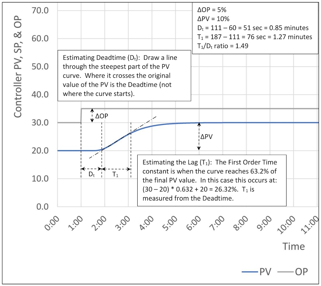
Figure 1 shows a step test for a process with a process gain of 2, three lags of 30 seconds and a deadtime of 30 seconds.
All open-loop tuning methods use this procedure. The only difference is how you calculate the tuning constants once you have the change in output, change in PV, deadtime and first-order time constant.
To execute a step test:
Step 1: Place the controller in manual.
Step 2: Step the controller OP.
Step 3: Estimate the change in PV, the deadtime (Dt), and the first-order lag time (T1) from the process reaction curve (a fancy way to say read them off the trend).
Step 4: Write down ΔOP, ΔPV, Dt and T1:
-
ΔOP = 5%
-
ΔPV = 10% (Verify that your system’s PID algorithm uses % of span internally.)
-
Dt = 0.85 minutes
-
T1 = 1.27 minutes.
Step 5: Calculate the baseline controller gain:
Kbase = ΔOP/ΔPV = 5/10 = 0.5
Step 6: Calculate and test.
While it is not necessary, calculating the lag/deadtime ratio will provide some insight into how well this PID controller can control the process.
In this case the lag/deadtime ratio is:
T1/Dt = 1.27/0.85 = 1.49
This is a moderate self-limiting process. Based on this we should expect that a PID controller can control the process, but we must be careful about the tuning. The controller gain will only be slightly above the baseline gain. The response to a setpoint (SP) change will be little faster than the process open-loop response and disturbance rejection will only be moderately effective.
PID tuning: Calculating tuning constants, simplified IMC method
There are reportedly some 400 to 500 published loop-tuning methods. I will discuss a few of the multiple methods later on, but to get you started, I will use a simplified version of the internal model control (IMC) method. The full IMC method includes a performance tuning constant (λ – lambda) that is used to set the controller response. Tuning for a specific type of controller response is beyond what we need to cover now. The simplified IMC method presented will provide adequate response for lag dominant, moderate and deadtime dominant self-limiting processes.

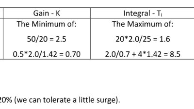
In “PID spotlight, part 6: Deadtime? How to boost controller performance anyway,” [link] we saw that how much controller gain we could safely apply to a PID controller was related to the lag/deadtime ratio. The controller gain calculation in Table 1 reflects this relationship; the baseline controller gain is modified by a variant of the lag/deadtime ratio (the calculation provides a roughly critically damped controller for true first order plus deadtime processes).
How did we do? Simplified IMC tuning, moderate process
Table 2 shows the simplified IMC calculations for the process that was tested in figure 1.

The calculated tuning constants are:
-
K = 0.63
-
Ti = 1.59
-
Td = 0.40 (if used).
At this point we enter the tuning constants in the PID controller and then test the results. Figure 2 shows controller performance for the PI tuning constants (derivative is set to 0.)

The response is too oscillatory to be considered critically damped. This points out an important aspect of using any loop-tuning method. Each one provides guidance that will get you close, but you may still have to trim the constants to get the exact performance you need. In this case the tuning calculations were set up for a true first order plus deadtime process, however the actual process has three lags plus deadtime. Because the actual process doesn’t match the theoretical process the calculations can only provide an approximate answer. That’s OK; in the real world you will never know exactly what your process is, so the best that you can expect is to get a reasonable approximation. You may need to adjust the tuning constants.
However, with all that said, we know that a moderate self-limiting process may benefit from the addition of derivative. Furthermore, in Part 6 of the article series, we saw that if the process has multiple lags then derivative will help performance. Figure 3 shows what happens when we add derivative.

The controller tuning is still more aggressive than critically damped, but not tremendously so. Adding derivative has, as expected, considerably damped process oscillations and PV overshoot of the SP on a SP change. If critically damped tuning is required the controller gain must be lowered.
PID tuning: A lag-dominant process open-loop test
Figure 4 shows an open-loop step test for a lag dominant process with a process gain of 2, three lags of 70, 10 and 10 seconds, and a deadtime of 0 seconds. The apparent deadtime of 10 seconds is caused by the presence of multiple lags.
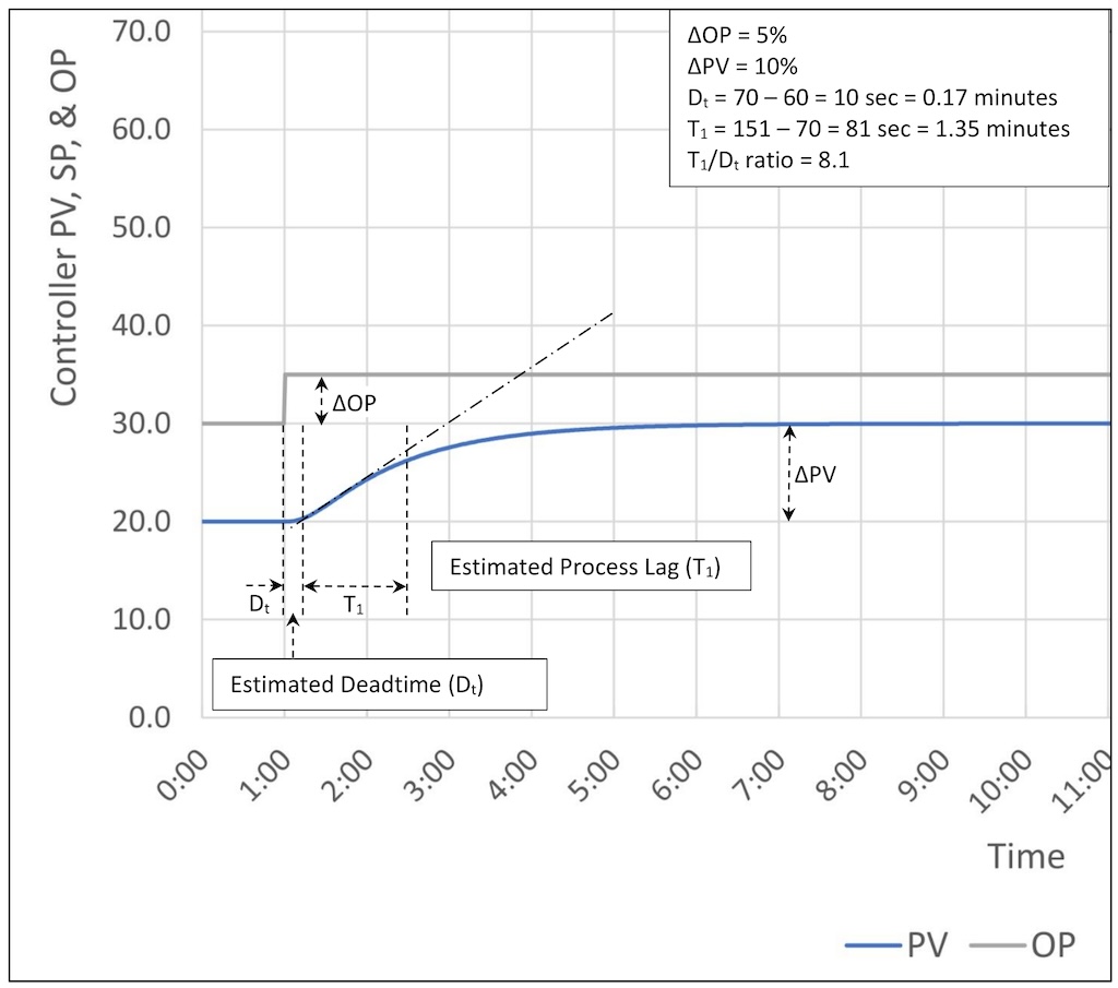
In this case the calculated tuning constants are:
-
K = 2.06
-
Ti = 0.89
-
Td = 0.22 (if used).
Figure 5 shows controller performance for the PI tuning constants (derivative is set to 0.)
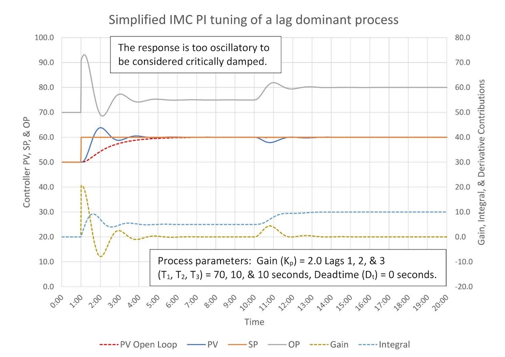
As expected, when we have a process with a higher lag/deadtime ratio (8.1:1 versus 1.49:1) we can use a higher controller gain (2.06 versus 0.63). We can see that the controller has better disturbance suppression: PV deviation from SP is ~2% versus ~5% for the moderate process.
The tuning is again more aggressive than critically damped and is oscillatory after a SP change. The tuning appears to be closer to optimal disturbance rejection. While derivative is not generally recommended for lag dominant processes, let’s take a look at adding derivative in Figure 6.
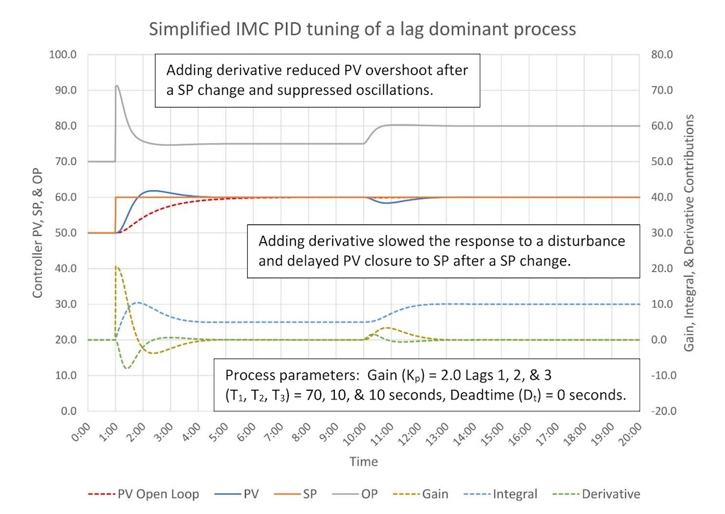
Adding derivative did considerably reduce the PV overshoot after the SP change and also completely suppressed oscillations. This looks like a good thing. Adding derivative also slowed recovery from a disturbance and delayed PV closure to SP after a SP change. This could be a problem.
A close look at the derivative contribution trend shows that derivative pulls back on the OP once the PV starts moving after the SP change, which limits PV overshoot. Derivative also speeds the initial response to the disturbance. However, because derivative penalizes PV movement, once the PV started returning to SP after the SP change and after the disturbance the derivative slowed the PV return rate.
From this example it looks like the use of derivative could add value depending on your goals. If limiting PV overshoot and oscillation suppression is important and delaying when the PV gets back on SP after a disturbance or SP change has a lower priority then adding some derivative might be worthwhile. The overall point is that while we have certain rules (like only use derivative on moderate processes), our overall goals should drive how we tune a controller. Rules can be helpful, but you cannot turn off your brain just because you are following a tuning method.
PID tuning: Open-loop test for a deadtime-dominant process
Figure 7 shows an open-loop step test for a deadtime dominant process with a process gain of 2, three lags of 10 seconds and a deadtime of 120 seconds.
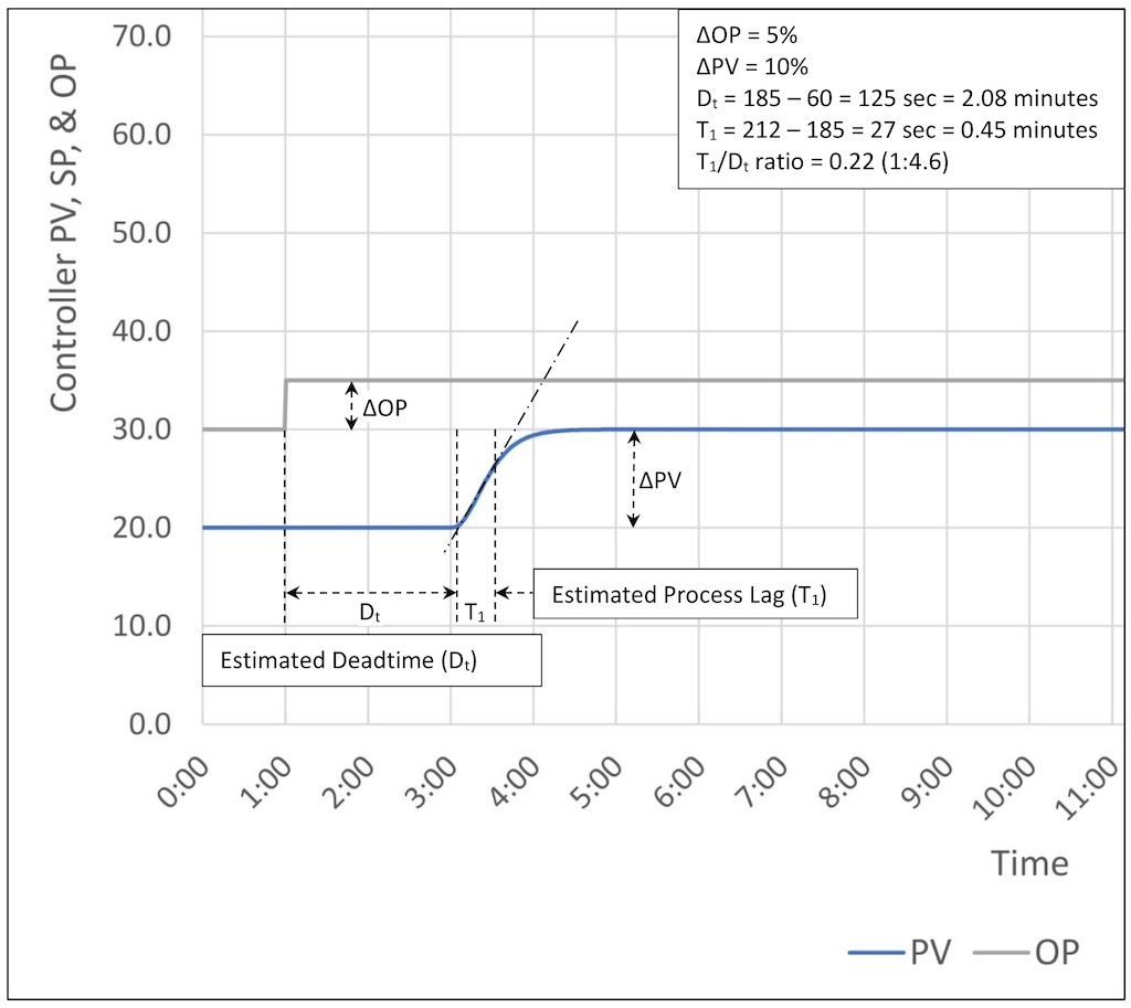
In this case the calculated tuning constants are:
-
K = 0.22
-
Ti = 1.88
-
Td = 0.47 (if used).
Figure 8 shows controller performance for the PI tuning constants (derivative is set to 0.)
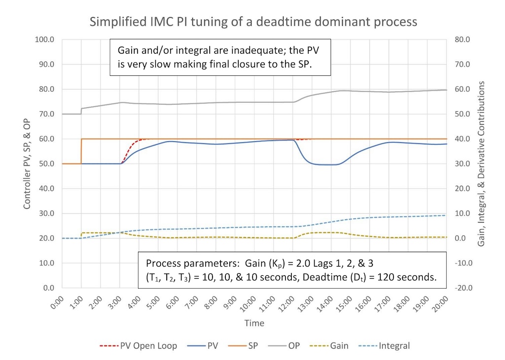
Unlike the tuning for the lag dominant and moderate cases the simplified IMC calculations gave us tuning constants that are too slow. The PV gets close to SP, and then drifts away for a while before the integral action finally brings it back to SP. Based on the examples of what bad tuning looks like in “PID spotlight, part 5: What does good and bad controller tuning look like?”
We might guess that this controller has too little integral (Ti is too big). This guess is correct; optimal tuning for this controller is controller gain (K) = 0.16 and integral (Ti) = 1.1. The upcoming article on heuristic tuning methods will show you how to find optimal tuning constants once you have made your first estimate using an open- or closed-loop tuning method.
To reiterate the point: Any open-loop tuning method will only get you in the ballpark. Sometimes no more adjustment will be required, but a significant number of controllers will need some fine tuning to get the response you need. Please avoid thinking that you can do a step test, plug the numbers in a spreadsheet and say, “My job is done!”
Finally, figure 9 shows controller performance for a PID controller applies to a deadtime dominant process.
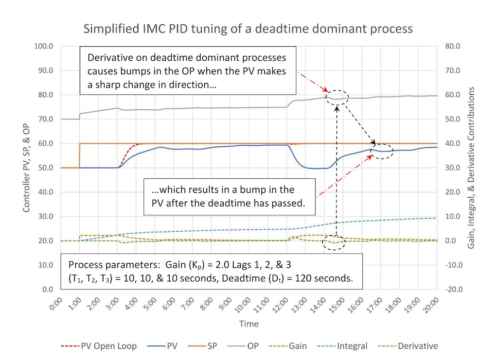
Figure 9 shows us why derivative is not recommended for deadtime dominant processes. The PV of a deadtime dominant processes will tend to run in one direction and then make a sudden change in direction. Derivative will respond to the sudden change in direction by bumping the OP, which will result in a bump in the PV after the deadtime has passed. This will in turn cause the OP to bump and the whole cycle starts over. In particularly bad situations this will create a string of bumps.
In general, derivative helps a controller look around a slow bend, which are more common in moderate self-limiting process. Derivative tends to overreact to sharp corners, which are more common in lag dominant and deadtime dominant self-limiting processes.
PID tuning: Three open-loop tuning tips
Three open-loop tuning tips are:
-
Make multiple steps when performing the open loop test (minimum of three).
-
The step sizes should be different.
-
The step sizes should be made in opposite directions. This is necessary to see if the valve is working. (A cascade master may not require multiple steps as valve performance should not be a problem.)
PID tuning: Open-loop tuning limitations
-
Slow control loops may be difficult to test. External disturbances may make it difficult to guess an ultimate gain and curve inflection point, which will make it impossible to calculate loop-tuning constants.
-
Bad valves will warp the results. Estimated ΔPV can be wildly inaccurate, especially with small step sizes. Deadtime may also appear variable based on valve response. (This is covered in more detail when we talk about bad valves.) As a matter of good practice before tuning an existing control loop, you should check the loop for valve problems and other non-loop tuning related problems.
Control tuning doesn’t just go bad; something has happened to a piece of equipment to cause the problem.
Ed Bullerdiek is a retired control engineer with 37 years of process control experience in petroleum refining and oil production. Edited by Mark T. Hoske, content manager, Control Engineering, WTWH Media LLC, [email protected].
KEYWORDS: Proportional-integral-derivative, PID tutorial
CONSIDER THIS
After you have executed an open loop step test, calculated PID controller tuning constants and entered them into your PID controller, are you done?
Follow the Control Engineering PID series from Ed Bullerdiek, process control engineer, retired.
Part 1: Three reasons to tune control loops: Safety, profit, energy efficiency
PID spotlight, part 2: Know these 13 terms, interactions
PID spotlight, part 3: How to select one of four process responses
PID spotlight, part 4: How to balance PID control for a self-limiting process
PID spotlight, part 5: What does good and bad controller tuning look like?
PID spotlight, part 6: Deadtime? How to boost controller performance anyway
