Programmable logic controller (PLC) programming languages help keep manufacturing operations running smoothly. Learn about the five types of PLC programming languages and how they’re used.
Learning Objectives
- Understand the five different types of programmable logic controller (PLC) languages.
- Learn how PLC programming languages work how they have evolved over the years.
PLC programming insights
- Programmable logic controller (PLC) programming languages have evolved along with PLCs themselves and are the foundation for how these machines operate efficiently.
- There are five PLC languages. Two are graphical: ladder logic (LAD) and function block diagram (FBD). Two are text languages: Structured text (ST) and instruction list (IL). Sequential function charts (SFC) is a graphical method of organizing programs for sequential or parallel processing.
To make a programmable logic controller (PLC) do what the user wants, it must be programmed. Programming can be done offline, after which the PLC program is downloaded to the PLC. Before the download process, however, the software checks the program for errors and compiles it into machine code.
Programs also can be edited online. When downloading a program, the processor must be stopped, and all control ceases; editing online allows changes to be made while the program is running, without interruption.
PLC program organization
Organization of a program is very important from a functional standpoint and so that operations can be found easily. Different platforms provide the ability to create tasks, programs, routines and sections.
All PLC platforms have a routine that is designated to run first. It is important when learning a new platform to identify which routine this is. This is sometimes known as the main routine.
As with data memory, the program itself can be organized in different ways. Major PLC platforms all have some form of subroutine, though they may be called by different names.
It is very important to consider whether memory will be global (available to all programs and routines) or local (only available to part of the program) before beginning a program. Think about whether or not you will have multiple instances of the same code.
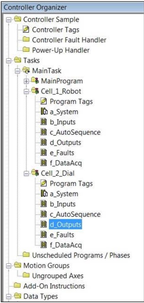
More powerful PLCs also may allow multiple programs to be placed into a task. While the programs are still scanned one at a time, this PLC capability allows data tables or tag lists to be assigned to one program, rather than being global. Programs then are scheduled to run in a specific order under the task. This also allows programs to be duplicated under different names, but with the same tag names. This allows for rapid code development, since a program can be written and tested then copied, addresses and all.
PLC programming languages (IEC 61131-3)
PLCs have evolved in different ways depending on the manufacturer. Programming software and methods of handling data can differ immensely from platform to platform. Because of this, the International Electrotechnical Commission (IEC) created an open standard in 1982 that defines what equipment, software, communications, safety and other aspects of programmable controllers should look like. After the national committees had reviewed the first draft, they decided it was too complex to treat as one document. They originally split it into five sections:
-
Part 1 – General information
-
Part 2 – Equipment and testing requirements
-
Part 3 – Programming languages
-
Part 4 – User guidelines
-
Part 5 – Communications
The standard currently is divided into 9 parts and a tenth part is being worked on.
The third part, IEC 61131-3, defines the languages that are used in programming. It describes two graphical languages and two text languages, along with another graphical method of organizing programs for sequential or parallel processing.
The graphical languages are ladder logic (LAD) and function block diagram (FBD). The text languages are structured text (ST) and instruction list (IL). The organizational method described above is sequential function charts (SFC), which is also graphical. An additional extension language is continuous function charts, (CFC), which allows graphic elements to be positioned freely; it can be considered as an extension of SFC.
The following examples illustrate the five IEC programming languages; the addresses used are generic, and the logic shows selection of auto and manual modes, along with a timer enabling cycle. These examples do not come from an actual programming language or brand, but are meant to illustrate uses of the languages.
Ladder logic (LAD) programming example
Ladder logic evolved from electrical circuit drawings, which resemble the shape of a ladder when drawn. As a graphical language, the instructions represent electrical contacts and coils. The vertical sides of the ladder diagram are known as “rails,” and the horizontal circuits are often called “rungs.”
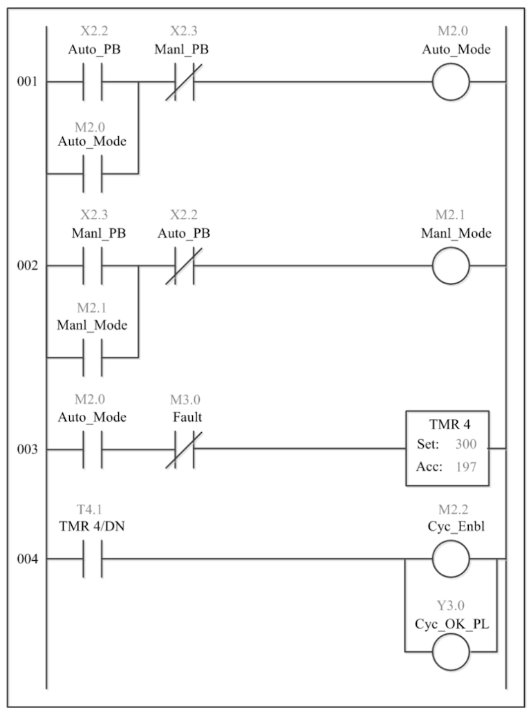
The “X” addresses represent physical inputs, while the “Y” address is a physical output. The “M”s are internal memory bits.
Because of the variety of addressing schemes as described previously, register representations can mean different things on different platforms.
When monitoring ladder logic in real time, usually contacts and coils change color to
indicate their state in the logic. If a path of continuity exists from the left rail to the coil, the address will be said to be “On” or “True”.
The timer shown in the diagram also may show a time base. If the above timer’s preset is three seconds, the time base would then be 10 ms.
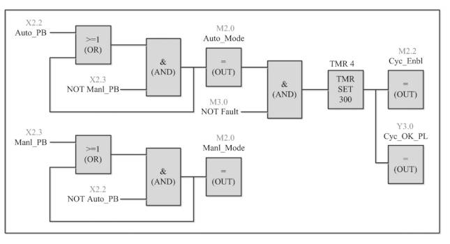
Function block diagram (FBD) programming example
The function blocks (FBs) evolved from Boolean algebra, the AND and OR representing basic logic. More complex blocks are used for math, loading, comparing and transferring data, timing and counting.
Some functions, such as XOR (Exclusive OR), cannot be represented in ladder logic. Also, because of the complex nature of some FBD drawings, logic can often extend across many pages. Off-page connector symbols are used to show these connections.

Instruction list (IL) programming example
Graphical languages are usually converted into a text language called Instruction List before being compiled into another low-level code called machine language. Before the advent of personal computers, handheld programmers were used to type instructions into the PLC before compilation. These devices often had pictures of ladder logic contacts on the keys.

Since IL is text-based, it is easy to manipulate in third-party text or spreadsheet editors, such as Microsoft Excel. Instruction List can usually be imported or exported to and from PLC software in the form of .csv (comma-delimited) files or XML (eXtensible Markup Language). This makes it easy to create tables of addresses or tags with a common structure in IL, and then convert it into many repetitive rungs or blocks with different addresses. When writing large amounts of repetitive code, this can save a lot of time.
Structured text (ST) programming example
Structured text resembles high-level programming languages, such as Pascal or C. Variables are declared as a data type at the beginning of routines as well as configuration of other parameters. Comments are shown in this program as starting with “//”; this may differ depending on the brand.
Linear programming languages, such as structured text, use constructs like “If-Then- Else”, “Do-While”, and “Jump” to control program flow. In these languages, syntax is very important, and it can be difficult to find errors in programming. Debug tools allowing for partial execution of the code one section at a time are common.

While writing PLC code in Structured Text can be difficult, it is also a much more powerful language than ladder logic or function block. Libraries can be developed to perform complex tasks such as searching for data using structured query language (SQL) or building complicated mathematical algorithms.
At the same time, since the program proceeds step by step, it is more difficult to respond to multiple inputs at the same time; program control can be complex with many loops.
Different PLC platforms may use a different designation for these IEC languages.
Sequential function charts (SFC) example
SFC makes use of blocks containing code that typically activates outputs or performs specific functions. In many platforms, the blocks or “steps” can contain code written in other IEC programming languages, such as Ladder or FBD. The program moves from block to block by means of “transitions”, which often take the form of inputs.
SFC is based on Grafcet, a model for sequential control developed by researchers in France in 1975. Much of Grafcet is, in turn, based on binary Petri Nets, also called place/transition nets. Petri Nets were developed in 1939 to describe chemical processes.
Steps in an SFC diagram can be active or inactive, and actions are only executed for active steps. Steps can be active for one of two reasons; either it is defined as an initial step, or in was activated during a scan cycle and not deactivated since. When a transition is activated, it activates the step(s) immediately after it and deactivates the preceding step.
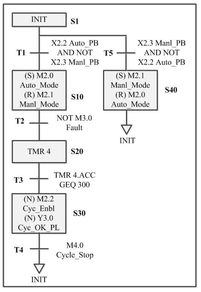
Actions associated with steps can be of various types, the most common being set (S), reset (R) and continuous (N). N actions are active for as long as the step is while set and reset operate as in the other PLC languages.
Actions within the steps and the logic transitions between them can be written in other PLC languages. Structured text is common in the action blocks, while ladder is often used for transitions. Steps and transitions are labeled as S# and T#. The top of the program will always contain an initial step; the program starts here, and this is also where it returns after completion. A program will scan the logic in a step continuously until its associated transition logic becomes true; after this the step is deactivated and the next step is activated.
How PLC programming languages work
The PLC processor or CPU controls the operating cycle of the program. The operating cycle, or Scan, consists of a sequence of operations performed sequentially and continuously.
There are four parts to the PLC scan cycle:
-
Read physical inputs to the input image table.
-
Scan the logic sequentially, reading from and writing to the memory and I/O tables.
-
Write the resulting output image table to the physical outputs.
-
Perform various “housekeeping” functions, such as checking the system for faults, servicing communications and updating internal timer and counter values.
The scan cycle can be visualized as shown in the diagram on the left. When the processor is placed into “run” mode, the state of the analog and digital inputs is captured and saved into memory registers dedicated to the configured inputs. In the second part of the scan, the logic is evaluated sequentially. If the program is written in ladder logic, the rungs are evaluated one rung at a time, left rail to right, top to bottom. As the logic is processed, output and memory coils are energized or de-energized, and their status is saved into their respective registers. In the case of the outputs, they are saved into the Output Image Table, which is generated during hardware configuration.
The time that it takes to execute a scan depends on the number and types of instructions in the program. Scans may be as short as 3 to 5 ms (a very short program or a very fast processor) or as long as 60 to 70 ms (a longer program).
If the scan time exceeds this period by very much, physical reactions of actuators start to become noticeable; it may be time to evaluate a change to a more powerful PLC processor or even use multiple processors.

PLC programming subroutines
An exception to the scanning method described previously is that of Allen-Bradley’s ControlLogix platform from Rockwell Automation. Instead of accessing the input and output image tables at the beginning and end of the scan, each I/O card is configured with a requested packet interval (RPI). I/O tables are updated at this rate.
Scanning begins with the first rung of the routine designated as the main routine; all PLCs have a routine with this designation. As logic is processed, calls to other routines will occur as shown. After a subroutine is scanned, the scan returns to where the jump or call was made. Eventually, the scan always ends at the end of the main routine.
The scan begins at the top of the main routine and is evaluated left to right, branch by branch, top to bottom. When the scan reaches a jump subroutine (also known as a “call”), the scan continues in the new routine, which is subroutine 1 in this case. Subroutine 1 then calls subroutine 2; when the end of subroutine 2 is reached, the scan continues in subroutine 1. When the end of subroutine 1 is reached, the scan continues back in the main routine.
Subroutine 3 is called, is scanned to the end and then returns to the main routine. When the end of the main routine is reached, the resulting output image table is written to the physical outputs, and the housekeeping functions (Step 4) is completed. The scan then starts over at the top of the main routine.

Scan times will vary from cycle to cycle, depending on the number of instructions and routines active at any given time, the load on the processor from “housekeeping” activities, and communications’ connections. Execution times for each type of instruction can be found in each manufacturer’s documentation.
Hardware also affects scan times; newer models of processor are much faster than older ones due to technology advances in technology.
PLC operational modes
PLCs can be placed into several operational states. When the processor is executing its program and scanning in the normal way, it is said to be in “Run” mode. When initially downloading a program, the CPU is in “Stop” or Program mode; it is not executing the program, and I/O is not changing state.
The mode of a PLC often can be changed by means of a switch on the front of the processor; for security, this may be a key. There is often a third position on the key switch labeled “Remote”; this allows a computer to be used to change the state or mode. This adds an additional layer of safety; when the switch is in Program or Run the state cannot be changed from the computer.
While the computer is connected, the program can sometimes be changed while the PLC is scanning. Not every PLC allows this, and it is not always done in the same way. Some platforms, such as Allen-Bradley, allow each line or rung of code to be changed while online followed by accepting, testing, and assembling (compiling) the program; others such as Siemens allow each block to be compiled and downloaded without interrupting program execution.
Additionally, many platforms allow the processor to be placed in “test” or “debug” mode. This allows breakpoints to be placed in the code to stop execution at that point. This can be useful if monitoring “looped” code.
– This has been edited from the “Maintenance and Troubleshooting in Industrial Automation” book by Frank Lamb, the founder and owner of Automation Consulting LLC and a member of the Control Engineering editorial advisory board. Edited by Chris Vavra, web content manager, Control Engineering, CFE Media and Technology, [email protected].
MORE ANSWERS
Keywords: PLC, programmable logic controller, PLC programming
CONSIDER THIS
What PLC programming languages do you use most often in your operations?