Tutorial: If you’re a Food Channel fan, as I am, you probably have heard Alton Brown talking about hardware and software as ingredients in culinary projects. Today, we’re going to talk about some of the hardware and software ingredients that go into mechatronic projects. For Alton Brown, software includes eggs, milk, water—all the “wet” stuff that goes into food.
|
If you’re a Food Channel fan, as I am, you probably have heard Alton Brown talking about hardware and software as ingredients in culinary projects. Today, we’re going to talk about some of the hardware and software ingredients that go into mechatronic projects.
For Alton Brown, software includes eggs, milk, water—all the “wet” stuff that goes into food. For mechatronics, software includes the operating system (OS), application programs, and instrument drivers.
At least, that’s what actually ends up in the final product. The mechatronics chef needs bits of ancillary software as well. Mechanical-design packages generally take computer-aided design (CAD) input describing the mechanical system, and create a finite-element model (FEM), which then reacts to forces and torques as the real mechanical system might be expected to react. Similarly, electronic design automation (EDA) software uses descriptions of the electronic components and interconnects to create a SPICE model of the electronic system, which reacts to the inputs and loads as the real electronics might be expected to.
| Mechatronic systems typically feature multiple nested control loops. |
Software
You need software tools to assemble the software as well. Microprocessors understand “machine code” — lists of instructions written as “op-codes” embodied in digital bits loaded into the computer’s memory registers.
While many computer scientists, and some engineers, still know how to program these machines directly, nobody wants to. Application source code is written in “human readable” languages, like BASIC, C, and Fortran. By the way, these human-readable languages are called “third-generation languages” (3GL) with machine code being the first generation (1GL). (And you don’t want to know about 2GL — trust me.)
The compiler is a software package that translates the human-readable source code into machine-intelligible machine code. Not only does the compiler need to understand the particular human-readable language, it also needs to fully understand the op-codes for the target microprocessor as well as the available resources in the final system.
Writing 3GL code is, frankly, best left to computer scientists and engineers. These languages are general-purpose tools with complex syntaxes and arcane command sets. Control engineers are better off with fourth-generation languages (4GL).
These are more often referred to by the more descriptive terms “framework,” “environment,” or “integrated development environment” (IDE). Examples are Eclipse (open source), LabView (from National Instruments), and any of the vendor-specific implementations of the IEC controller languages. They are highly application-specific.
Target system
For most professional software engineers, and virtually all embedded-system engineers, the computer sitting atop their desk is not the target system. When writing software to run on a computer not the same as the one you are using, you need a ”cross compiler,” which runs on your computer but creates machine code that will run on the target computer. Software that runs on the target system includes:
-
Operating system , which mediates the use of processor resources (i.e, memory, bus access).
-
Instrument drivers , which give the application program access to peripheral resources ( i.e, sensors and drives).
-
Application programs , which control program flow, and perform logical operations and mathematical calculations.
| Control engineers most often work with fourth generation computer languages that simplify writing of specialized programs, such as mechatronic controller applications. |
Mechatronics applications generally call for real-time operation. The “real time” part comes from the operating system (OS). There are a number of choices for real time operating systems (RTOSs). A number of vendors offer proprietary RTOSs, such as VXWorks from Wind River. Microsoft provides real-time versions of three flavors of Windows (CE, XP, and Embedded). Others (such as Montavista, Wind River, Green Hills Software, and Lynuxworks) provide real time versions of Linux.
Instrument drivers tell the peripheral hardware what to do. By including the appropriate drivers for the instruments used in the project when building the software, the compiler makes it possible for the 3GL code to communicate with them. The instrument manufacturer writes the drivers and the compiler takes care of fitting them into the final machine code appropriately. All the mechatronics engineer has to do is make sure the correct drivers are available at compile time.
The application program is where the mechatronics engineer gets creative. It runs on the target controller and incorporates all the wit and wisdom needed to make high-level control decisions.
Is there a pedestrian stepping into the path of the automatically guided vehicle (AGV)? The application program must recognize that and plan appropriate action. The driver’s firmware might have to make the vehicle swerve in the right direction by the right amount, but it’s the controller application that decides the direction to swerve and by how much.
Hardware for mechatronics
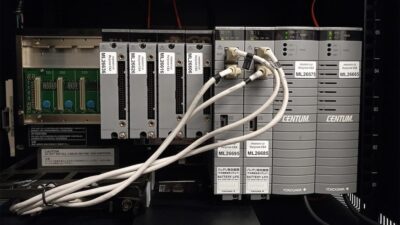
That brings us back to the hardware that puts the software decisions into practice. The controller is the hardware that does it, and choices vary widely. For large, stationary projects, a traditional programmable logic controller (PLC) or programmable automation controller (PAC) may be a good option. Engineers comfortable with data acquisition and control systems often opt for PC-based control, using multifunction cards and signal conditioning modules to provide I/O.
A growing cadre of mechatronic engineers, however, are taking the embedded-system approach. Kontron, for example, provides single-board computer (SBC) solutions in a variety of form factors. Freescale Semiconductor, Via, and Texas Instruments provide system-on-chip (SOC) devices that combine processors, I/O, memory, and even networking capabilities in one monolithic IC. I’ve seen 4-bit processors the size of a grain of rice, and multicore ICs with — let’s just say “a whole lot of” processors in one package.
Typically, an engineer specifying an embedded approach will design the motherboard that carries all the controller components. Many IC manufacturers, such as AMD, provide circuit boards or kits for users to make their own motherboards. There are also lots of other companies would be happy to help as well. Googling “custom circuit board fabrication” returned “about 115,000” hits!
The correct choice for your next mechatronic project depends on where your comfort zone lies. If, for example, you happen to be a veteran C programmer with Linux experience, you’ll probably be best off with an SBC running real-time Linux. If, on the other hand, you’re coming from a traditional machine control background, your first choice might be a PLC running Function Blocks. Motion control mavens might lean toward some of the offerings from Yaskawa (who, by the way, invented mechatronics in the first place).
The thing to remember is that there is no one best choice. It is a matter of adapting the hardware and software you are most familiar with from your previous control system experience to the mechatronic application at hand.
| Author Information |
| C.G. Masi is a senior editor with Control Engineering. Contact him at [email protected] |
What FPGAs can do for you
A field-programmable gate array (FPGA) is a embedded processing IC that uses a reconfigurable matrix of computing elements to implement a software design in hardware logic. Unlike the fixed computing functionality of traditional microprocessors and DSPs, FPGA devices literally rewire their internal structure to implement a computing task. FPGA designs are completely parallel in nature, so the various application subsystems can operate independently and simultaneously using dedicated hardware resources.
The process of translating software code into a highly optimized hardware implementation in FPGA “fabric” is called synthesis. Since there are multiple possible hardware implementations that could satisfy the requirements, an FPGA compiler must execute a complex optimization, routing and verification process. The end result is a high performance, high reliability hardware implementation of the design in the form of a bitstream that tells each hardware element in the chip how to configure itself. In effect, the software design is translated into the hardware domain.
| A single FPGA can replace thousands of discrete components by incorporating millions of computing elements in a single chip. |
FPGAs provide the ultimate in design flexibility and parallelism. Typically, designers partition the application between the FPGA and a conventional processor. FPGAs are often used for implementing the lower level I/O interface to sensors and actuators, performing time-sensitive control and signal-processing tasks, as well as communicating with specialized peripheral devices or external circuits.
For example, a designer implementing a multi-axis motion control application might use a processor for tag-based communication via ModBus, high level supervisory control, floating-point motion trajectory generation algorithms, and data logging. In the FPGA, he or she might choose to implement the higher speed and more custom parts of the application, such as the position encoder and current sensor interfaces, pulse width modulation (PWM) and motor commutation, spline interpolation for the motion trajectories, cascaded PID control loops for current, position and velocity, safety interlocks, and so on.
In the FPGA, there is no penalty (other than power consumption) for running each subsystem as fast as possible, since they do not compete for processing resources. Furthermore, FPGA programmers can literally customize each part of the application down to the logic-gate level to meet their unique requirements. Also, the FPGA is still reconfigurable after its deployment to the field, meaning that updates to the system or the addition of new features are much less likely to require a re-spin of the hardware boards. For these reasons, an upfront investment in FPGA programming can both improve time-to-market and reduce support and maintenance costs over the product’s lifetime.
Brian MacCleery, Senior Product Manager, National Instruments


