Tutorial: Labeling machines are commonly used as part of the packaging process and must be precise. The setup process for wiring and programming can be complex; here’s how make it simpler.
Learning Objectives
- Knowing product data, label data and camming details help with wiring and programming a labeler machine complexity.
- A function block called a labeler keeps track of four types of data: Product, label, label camera and camera control.
Learning about hardware wiring setup for a labeling machine, creating cams for the product and label and programming servomotor and motion control application code for a labeling machine may help for other motion control applications. To speed up the development process, an IEC 61131-3 function block called “labeler” is something users can incorporate into the coding process that improves the ease of use. A prior article discussed how software can help in selecting appropriate servomotors for the motion control application.
Wiring, digital inputs, motion control application
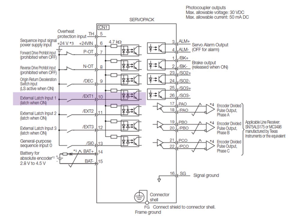
One product is a single-axis controller that provides a servopack amplifier capabilities for automation systems while offering 1.5 axes of built-in motion control in one package. The below diagram shows the digital inputs section from the hardware manual. Note for other controllers wiring diagrams will differ and should be reviewed based on product type.
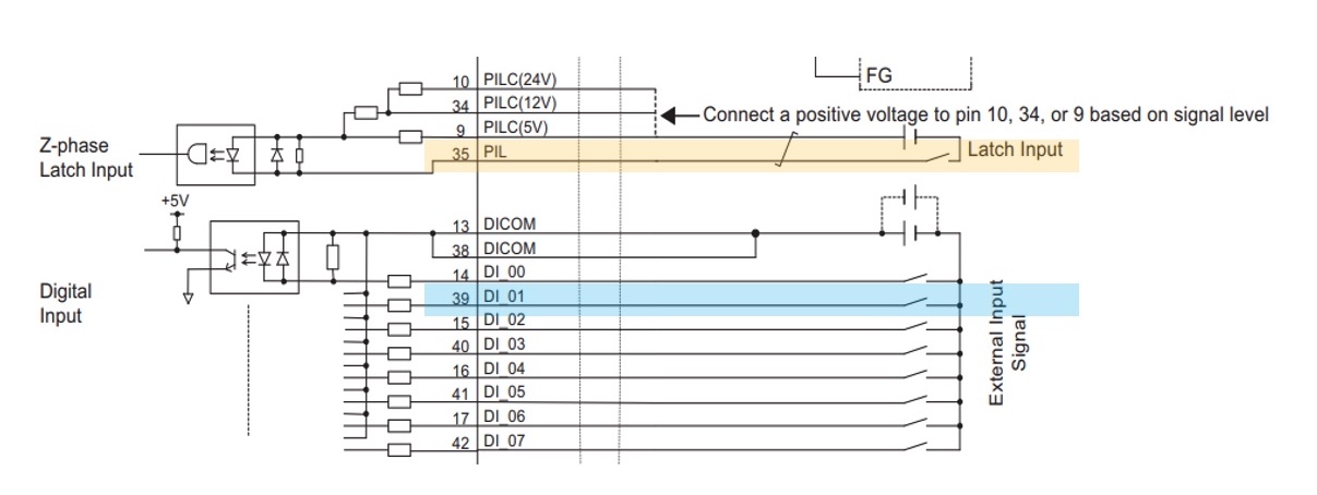
The application has two main inputs. The first input to highlight is the high-speed processor-in-the-loop (PIL) latch input updating at 5 microseconds (ms) or less for the label. The second input is the D1_01 (Digital Input 01), which updates at 600 ms for the product. Depending on the application and voltage, users should select the proper input.
Why use the PIL latch input for the labels? Labels are generally smaller pitch distances and due to these reduced distances, the label should be dedicated to a faster input. This allows for high-speed captures for compact distances that require optimized processing and cycle time.
Conversely, why use the DI_01 for the products?
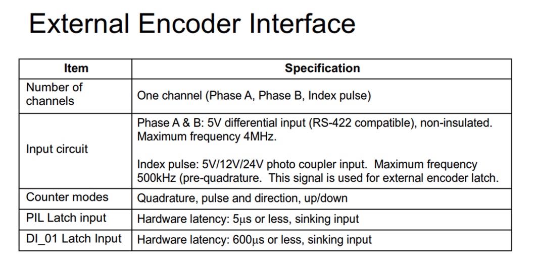
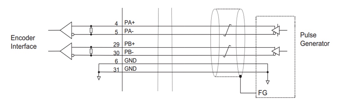
The product pitch distances are often longer and allow for more dedicated time to act upon the input of the product. Compared to the labels, this leaves more time to process and buffer the inputs. An external encoder is usually mounted onto the web (master) conveyor that carries the product. The product sensor buffers the position of the product from the external encoder through DI_01. In this way, the servo can apply the label at the correct position at the peel plate based on the external encoder input. The figure below details the external encoder interface.
A dedicated high speed latch input located on the digital, networkable servo amplifiers also could be allocated for additional high-speed inputs. This input updates at a rate of 15 ms. The /EXT1 (External Latch Input 1) below is similar in function to the PIL in Figure 1. The location of this high-speed latch input is on the servopack connector.
Servo motion programming fundamentals for users
The CamEditor tool is software that provides users the ability to quickly construct and visualize a cam profile (Figures 5 and 6).

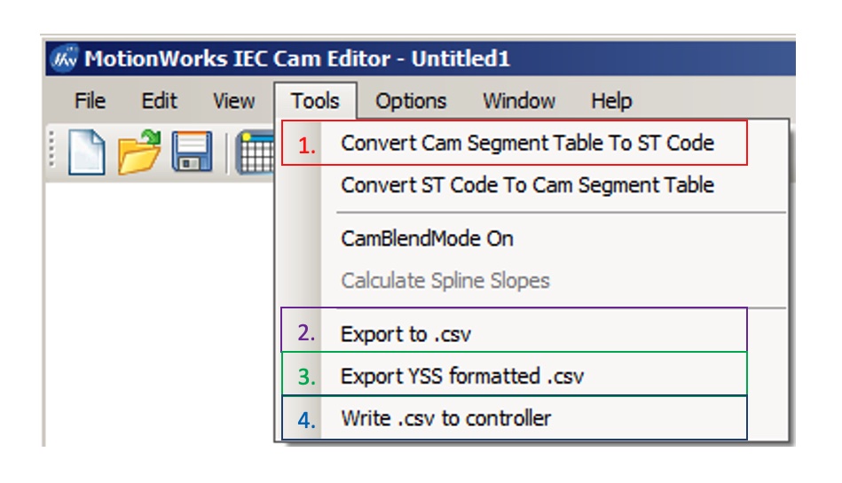
With this tool, users have four options below to construct the segments within the cam and use specific function blocks to create a table of points for a master/slave relationship:
- Structured text – where the user can identify the type of cam curve, segments and resolution for the cam profile.
- Export to a .csv file – allowing the user to have a specific set of points already constructed, usually in the form of two columns.
- Export to a .yss file – the file extension to use the cam profile within the software for the correct motion profile.
- Write a .csv file directly to a motion controller – skip any extra steps and save the .csv file onto a motion controller to directly access the points constructed and use the cam.
The software allows users to interact and change sizing capability regarding the mechanics. Instead of commanding aggressive motion profiles, the smooth accelerations and decelerations give machines a much longer lifecycle.
The diagram below shows an overview of using the CamEditor in collaboration with some IEC 61131-3 function blocks.
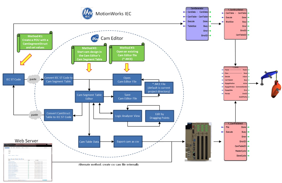
In summary, there are three methods for using the cam files.
Method one allows users to create a programmable organizational unit (POU) with a function block called ‘CamSegmentStruct’ and set the values necessary for other IEC 61131-3 function blocks without the need for the CamEditor. This is best used when the segments are known and the visual CamEditor is not needed.
Method two uses the CamEditor ‘CamSegmentTable’ by visualizing the curve and points allowing the user to modify the points on the fly.
Method three lets the user open a preexisting CamEditor file to modify any points required.
One function block example for a servo motion application
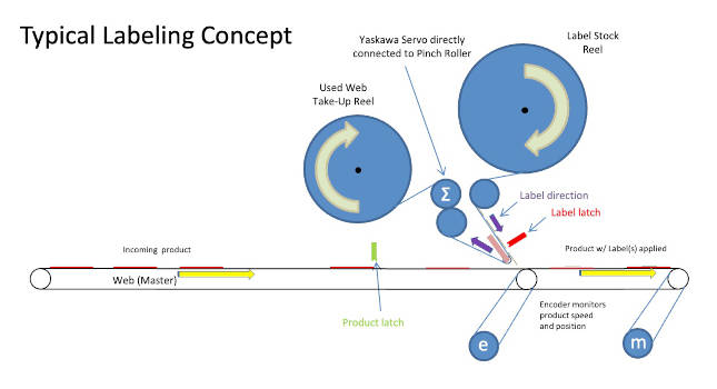
From the previous article, the diagram below shows an overview of a labeling systems layout.

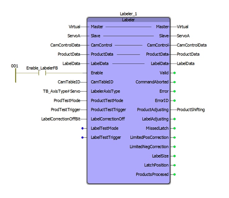
A function block called labeler can mitigate the complexity of labeler programming. This function block wraps all the details required into a convenient package. There are four main concept subcategories of information needed to use this function block:
- Product data
- Label data
- Label cam data
- Cam control data.
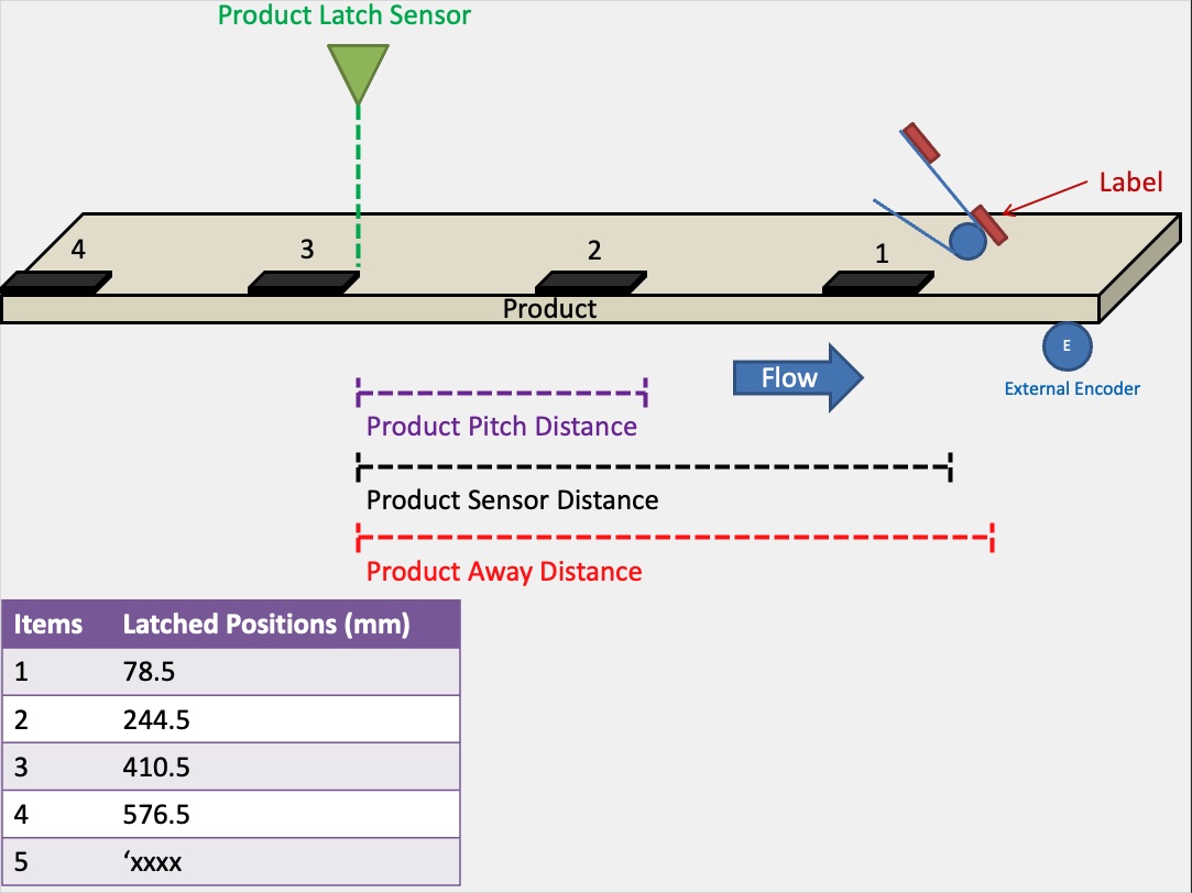
Product data contains the details about the product axis, which is generally the web master axis. For example, the product axis will have many latches from the product passing under the product latch sensor. Therefore, it makes sense to have a buffer where all these latched positions will be stored. There should be a sufficient size of latches to store. Anywhere from 10 to 20 latches should be more than enough. Also, knowing the physical distance from the product latch sensor to the beginning placement of the label is beneficial as this distance must be greater than 2 times the product pitch distance.
Buffering for multiple positions
For example, with a distance between products roughly 166 mm, the product sensor distance should be at 332 mm, (166 mm * 2). This will allow full capture of the product positions and use the buffer for multiple positions.
One other unique variable to know or calculate is called a product away distance, where the controls will know when the product is safely away to use the next position. This is often a distance a little greater than product pitch distance.
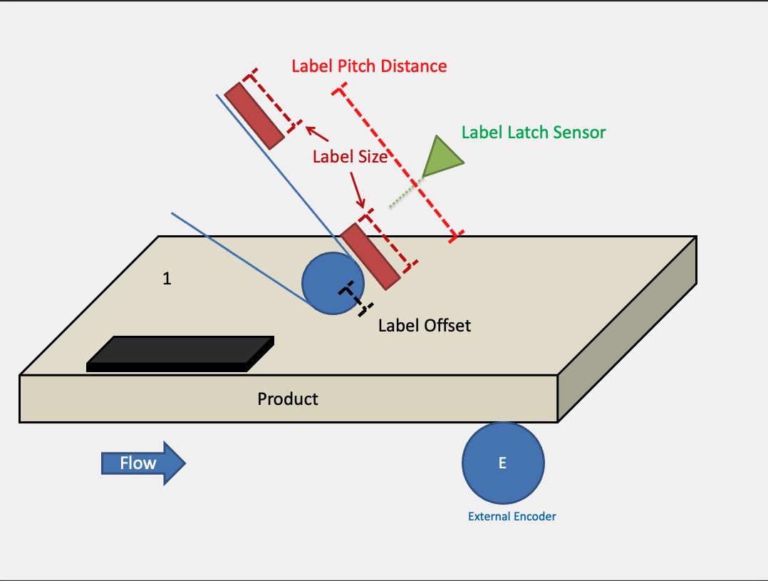
Label data contains the details about the label axis being applied to the product. Typical items required are the label size, label offset and the label latch sensor.
The label size is the distance between the marks on label supply. This will be in label axis units such as mm. The label offset is how much overhang the label must be located from the peel plate so it is already peeled a bit before applying the label to the product. The label latch sensor will be used from the label axis and must be allocated to receive the latches. It also must be within one label pitch distance.
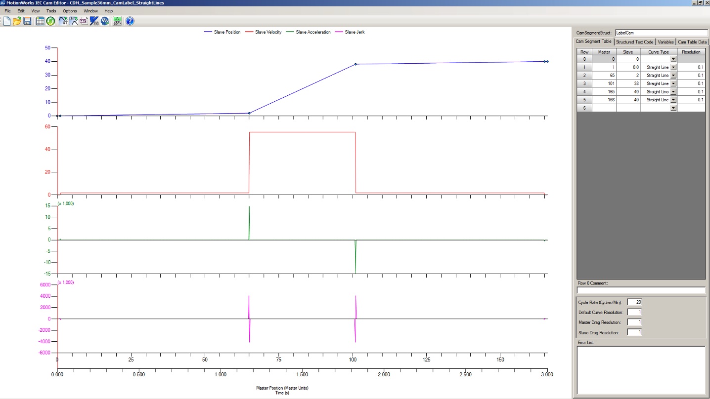
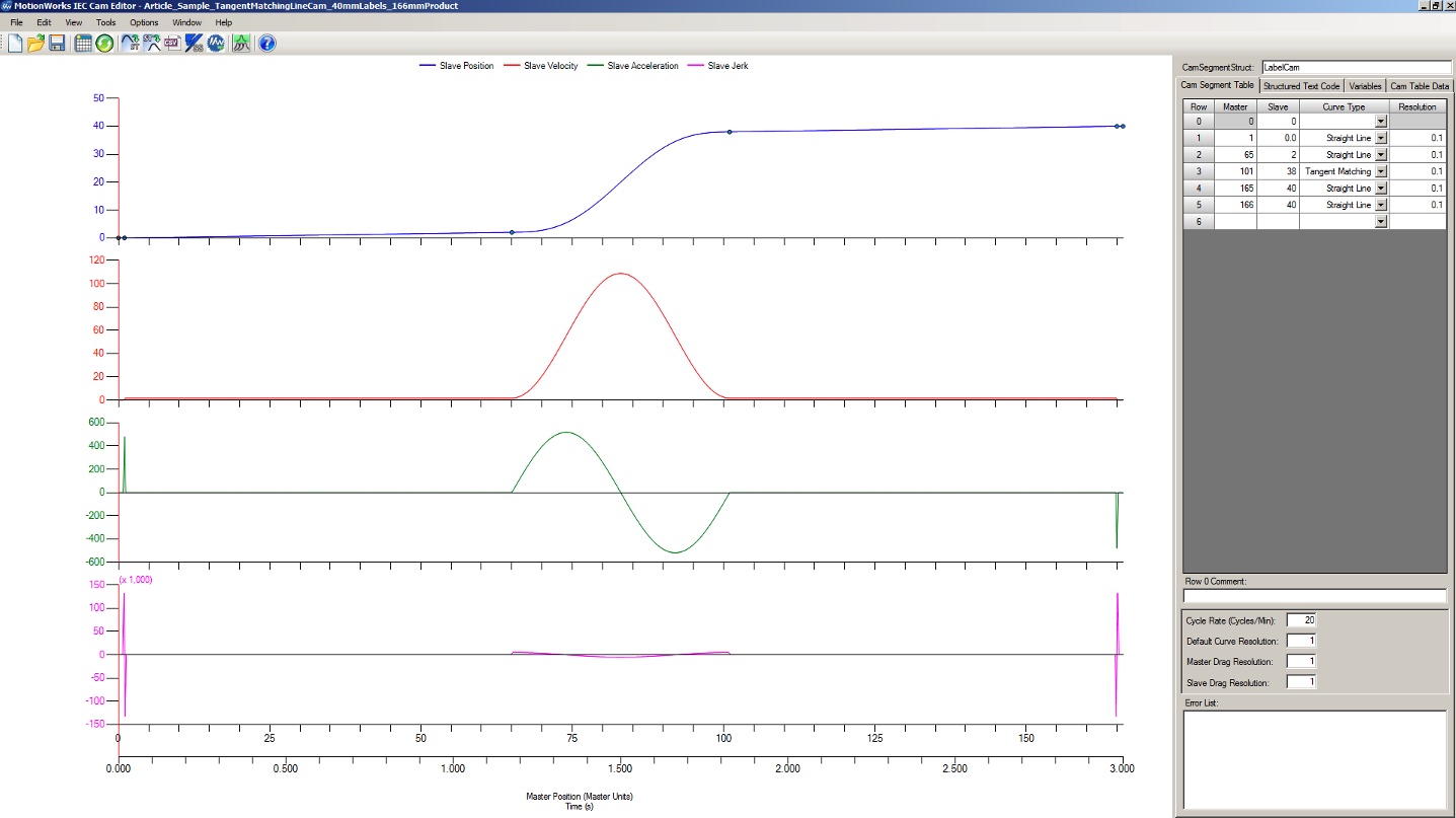
The label cam data is specific to the labels being applied on the product using the product data. This is created using multiple segments within the CamEditor tool. With the product data at 166 mm, the 40 mm label must be applied within this cycle. The easiest way to start creating this cam is using straight line segments to visually see the cam. See figure 12 as an example:

Multiple segments smooth motion
With products 166 mm apart, the master cycle will be from 0 to 166 mm for the master cycle and the slave cycle will be from 0 to 40 mm. However, this is a rough cycle with no provisions to the acceleration and deceleration on the label axis.
This will cause aggressive motion. To prepare for smoother operation, it is best to create multiple segments in between the master cycle. This can be done by adding straight line segments from 0 to 1 mm, then from 165 mm to 166 mm.
Finalizing the cam with different curve types, smoother operation of the axis can be achieved. The figure below shows smooth accelerations and decelerations. Notice the green line Slave Acceleration is different from the above straight-line segments.
Finally, the cam control data contains the upper management of the entire cam system. Items included are the modes of operation, synchronization positions and a safe engage distance. The modes of operation are either a one-way slave motion or a reciprocating slave motion. A start synchronization position is usually the first master position where the slave is synchronized with the master. The next position often represents the center of the synchronization zone.
This can be equal to an equation based off a start and end position. The final synchronization position should correspond with the end of the master cycle. Adjustments can be made within all areas of the process. A key position also would include a location in the process where the machine must decide to start the disengage process, continue camming or shift to the next product. A safe engage distance is usually the product sensor distance minus a small amount.
With all this information, the labeler function block can now be used to control a labeling axis.
Labeling applications can be made easy once key concepts are understood. The main points are knowing the product data, label data and some camming details. Adjustments can be made within software to accommodate for inconsistencies within the products and/or labels. While distances may vary, using the right software tools and technical expertise can help ensure success when wiring and programming.
Sixto Moralez is a senior regional motion engineer for Yaskawa America Inc.; Matthew Hardenbergh is the northeast regional motion engineer at Yaskawa America Inc. Edited by Chris Vavra, web content manager, Control Engineering, CFE Media and Technology, [email protected].
MORE ANSWERS
Keywords: labeler machine, function blocks
LEARNING OBJECTIVES
ONLINE
See additional stories at Discrete Manufacturing
CONSIDER THIS
What additional considerations should be given when wiring and programming?