Understand the advantages of multi-level output drive topology in medium voltage (MV) motor applications. Motor insulation reliability and reflected waves: What to consider when selecting a variable frequency drive (VFD).
Learning Objectives
- Review the fundamentals of variable frequency drives and motor insulation reliability considerations, including reflected wave.
- Understand multi-level cascaded output medium-voltage drives.
- Learn about resonance and motor insulation reliability considerations and the need to reduce risk of insulation breakdown.
Multi-level output drive topology insights
- Understanding the impact of reflected waves may require reviewing the fundamentals of variable frequency drives and motor insulation reliability.
- Multi-level cascaded output medium-voltage drives require effective strategies to mitigate the risk of voltage reflections on motor insulation systems, especially in applications with long motor cable requirements.
- Resonance should be considered for reducing risk of motor insulation breakdown and motor reliability.
Variable frequency drives (VFDs) are common in most industrial motor applications, including pumping, compressing, blowing, conveying, extruding and mixing. When motors are started across the line on 60Hz utility power, efficient motor operation is limited to a very narrow window around the rated motor operating speed and torque values. Drives allow motors to operate at their optimal efficiency over a wide range of speeds, satisfying a wide range of varying torque requirements, while reducing motor stress and starting inrush current.
Fundamentals of variable frequency drives
For every motor, the optimal supply voltage and frequency changes as the speed and torque requirements of the application change. When started across the line, a 460V 60Hz motor only can operate at the utility supplied voltage and frequency. Drives overcome this limitation by continuously adjusting the output voltage and frequency to match the optimal operating conditions for the application load.
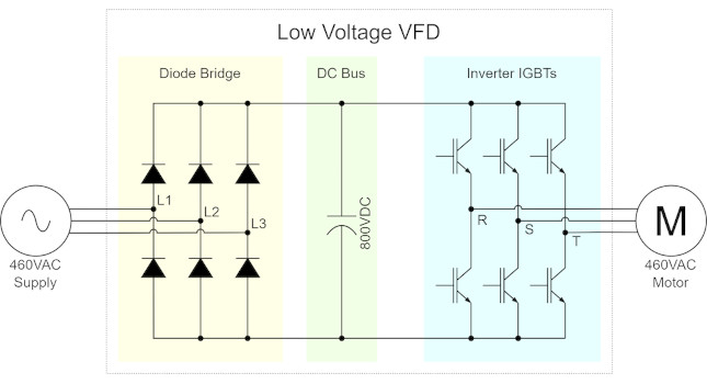
Most common low voltage (LV: less than 1000V) drives are comprised of three sections. Power flows from left (utility supply) to right (motor) in Figure 1.
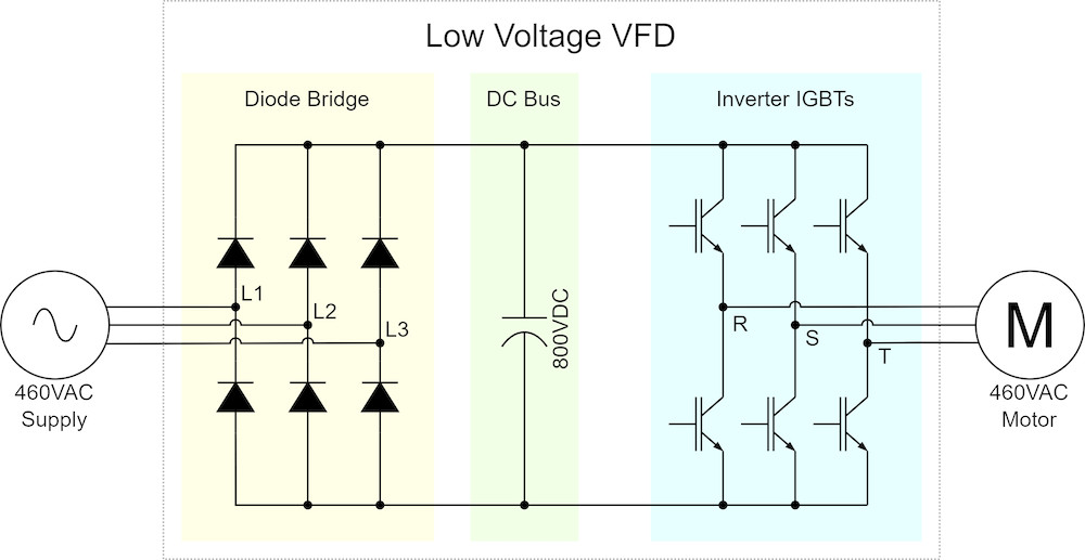
The diode bridge converts three-phase utility supply power from alternating current (AC) to direct current (DC).
The DC bus acts as a battery. The bus stores the energy it receives from the diode bridge until that energy is needed by the inverter section.
The inverter IGBTs (IGBT stands for insulated-gate bipolar transistors) are switches that turn on and off at a very high rate of speed (thousands of times per second). A drive cannot create a true analog sine wave output to match the utility supply. However, by using pulse width modulation (PWM), the drive generates a series of short pulses and long pulses that, when averaged, are representative of a sine wave voltage waveform, as shown in Figure 2. When smoothed by the inductance of the motor windings, the resulting motor current is approximately sinusoidal.
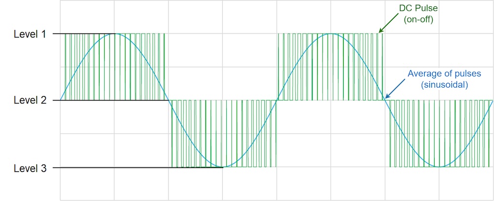
Example: This is similar in principle to using a dimmer switch with an incandescent light bulb. The dimmer switch doesn’t actually reduce the peak voltage to the light bulb, it just switches it on and off quickly enough that the pulses are not perceived, and the average illumination is reduced.
Motor insulation reliability considerations: Reflected wave
When the drive can be installed in close proximity to the motor (within 50m), no further consideration is typically required. The inductive and capacitive properties of the motor cables are dependent on length. When the cable length is short (<50m), the cable inductance and cable capacitance is generally small enough to have negligible impact on the system.
In some applications, it is not possible to install the drive near the motor. As the cable length increases, the inductive and capacitive properties of the cable become significant. When the high frequency PWM pulses travelling on the motor cable are reflected by the dissimilar impedance of the motor windings, the resulting voltage reflections will sum with the incoming pulses. The magnitude of this voltage reflection at the motor may be as much as twice the peak voltage value at the drive output. Without additional precautions, the high voltage stress created by reflected wave phenomena can exceed the cable or motor insulation system ratings and result in insulation breakdown and subsequent motor or cable failure.
NEMA MG-1 Section IV Part 31 addresses the risk of voltage spikes by requiring that motors intended for use with VFDs, or “inverter duty” motors, be designed with insulation systems capable of withstanding twice the rated peak (Vpeak = √2*VRMS) value of the supply (plus a 10% buffer). When applying VFDs, it is important to ensure the motor insulation system specified is appropriate for use with a drive and not intended only for use on utility line power.
Another common solution is to use load reactors, dV/dt filters, or sine wave filters at the output of the drive. Adding inductance at the drive output increases the rise time of each pulse, which results in a smoother waveform, and reduces the magnitude of wave reflections at the motor. While effective for reducing voltage spikes, the addition of output filters increases the overall cost, weight and footprint of a drive system, introduces a voltage drop, generates additional heat, and reduces overall system efficiency.
Multi-level cascaded output medium-voltage drives
For motors under 250HP using low voltage drives, increasing insulation ratings and applying output filters are effective strategies to mitigate the risk of voltage reflections on motor insulation systems, especially in applications with long motor cable requirements.
The same mitigation strategies can also be applied to larger drive applications. However, for applications above 250HP, it becomes increasingly economically feasible to consider using a multi-level medium voltage drive topology. With a multi-level drive output, it is possible for the drive to create a nearly sinusoidal output waveform, eliminating the risk of reflected voltage stress at its source.
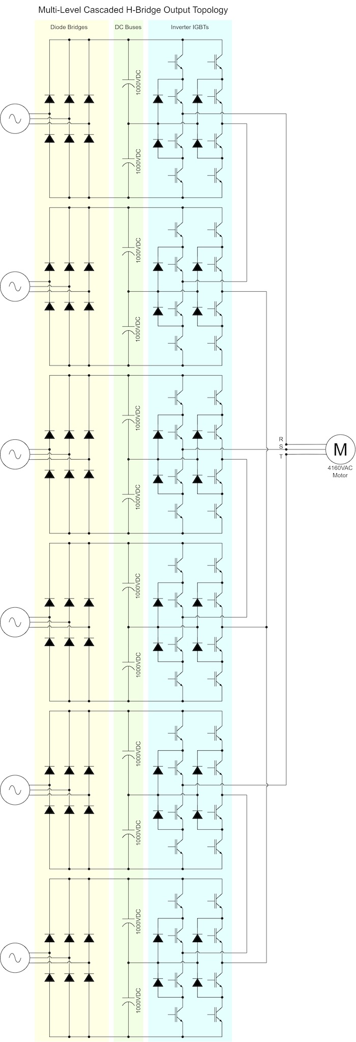
Most multi-level drives are constructed with the same basic building blocks as a typical low voltage drive (diode bridge, capacitor bus, and output IGBTs). Instead of switching a single DC bus potential on and off, multi-level drives use a cascaded topology in which the potential from multiple capacitor DC busses are summed in a series of smaller steps. As a cascaded waterfall flows over a series of small steps, a cascaded drive topology allows the output voltage to make smaller gradual steps, instead of switching from full ON to full OFF (as shown in Figure 2).
The 3-level output drive topology shown in Figure 1 is comprised of one DC bus to store energy, and six switching IGBTs to create the output three-phase waveform.
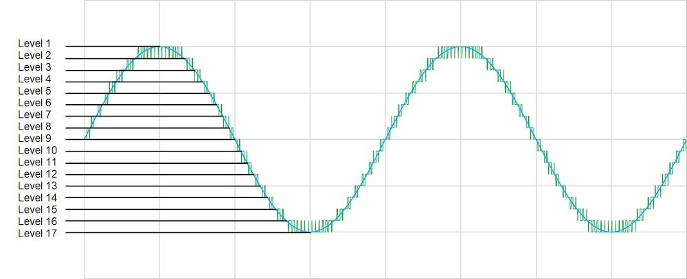
The 17-level output drive topology shown in Figure 3 is comprised of 12 independent DC busses to store energy, and a total of 48 cascaded IGBTs. Instead of switching the full output voltage, each of the cascaded IGBTs switches a small fraction of the full output voltage. The resultant output voltage waveform seen in Figure 4 is smooth and nearly sinusoidal.
A smooth cascaded output waveform inherently resolves the reflected wave voltage stress challenges faced by most LV drive topologies. Eliminating high amplitude switching pulses at the source reduces the need to add costly filters to protect against reflected wave phenomena at the output. A smooth 17-level output waveform reduces voltage stresses, increasing the service life of cable and motor insulation systems.
Motor insulation reliability considerations: Resonance
It is important to note that reflected wave phenomena is not the only potential source of harmful voltage stress in drive systems.
Resonance occurs when oscillatory forces are synchronized with the natural frequency of a system.
Example: When a child randomly swings legs on a swing set, that causes the swing to oscillate at a very small amplitude. When the frequency of the small leg “pumping” forces are synchronized with the frequency of the swing oscillation, each small force is added to the energy of the system, incrementally increasing the amplitude of each swing. If the swinger continued to pump after maximum amplitude is achieved (when the chains go slack), the resonance of the pumping action would cause the system to become unstable.
In applications with very long motor cable lengths (typically greater than 300m), electrical resonance of the cable system also must be considered. Modern voltage source drives modulate the output voltage by switching IGBTs on and off thousands of times per second (“pumping”). This carrier frequency is typically expressed in kilo hertz (for example, 4kHz = 4000 cycles per second). The combination of the inductive and capacitive properties of any cable has a unique resonant frequency. When cables are less than 300m, the resonant frequency is typically much greater than the drive carrier frequency, and poses little risk of excitation. As the cable length increases, the cable resonant frequency decreases. When the cable frequency and the switching frequency are equal, damaging resonant voltages of up to five times the peak voltage amplitude may be induced.
For applications with very long cables (over 300m), a study of the drive and cable characteristics should be completed to evaluate potential risk and identify an appropriate sine wave output filter to prevent resonance.
Reducing risks of insulation breakdown
For applications that require long motor leads, multi-level cascaded output medium voltage drives provide all the benefits common to all VFDs, while reducing the risks of insulation breakdown from reflected wave voltage spikes.
For legacy applications using motors with standard insulation systems (designed only for operation on 60Hz line power) multi-level cascaded output drives provide a reliable option to retrofit systems to variable frequency control without introducing additional voltage stress.
Lucas Paruch is a product manager of medium voltage drives at Yaskawa America Inc. Edited by Mark T. Hoske, content manager, Control Engineering, CFE Media and Technology, [email protected].
KEYWORDS: Medium-voltage drives, medium voltage motor maintenance, VFD tutorial
CONSIDER THIS
Have you considered the latest medium-voltage drive technologies?
ONLINE
Software tools can help when working with VFDs