Control software engineers seek control system solutions well beyond computer software programming. Understand seven critical phases of software engineering workflow for control system design and its worst enemy.

Control software engineering insights
- Educational requirements for control software engineers require knowledge of control software engineering requirements and processes.
- Seven phases of software engineering workflow benefit control system design.
- Phases 1 and 2 include the most dangerous enemy of control system design.
Automation applications and those programming and working in automation and controls can benefit from improvements to software engineering skills. Software engineering is a relatively old term; its first mention goes as far back as the 1960s. However, there are other terms that may sound similar, like software design, computer programming, controller design, etc. How do they differ? Generally, software engineering contains software design, computer programming and other relevant activities, but it contains other, typical engineering activities to be explained below.
Another difference between a software engineer and a software designer, for example, might be in their goals. While a software designer’s goal is to create a software/computer program, for a software engineer such a software/computer program is just a tool for achieving “higher” goals. This is especially true for the control software engineers, who would target a certain control system solution.
Educational requirements for control software engineers
Control software engineer education should include some engineering education, including knowledge and experience control systems design. This involves knowledge of control theory and electronics. To become a proficient computer, microcontroller (MCU), or digital signal processor (DSP) programmer, some basic, computer science knowledge and strong knowledge of certain programming languages. A good understanding of MCU/DSP hardware is important, especially if the final product will be an embedded system, a typical “subject” of the control software engineers.
An embedded system is a specialized computer system designed for specific tasks within a larger mechanical or electronic system. It is essentially a computer built into a specific device to control its functions, often with a focus on real-time performance. If such device is a kind of a control system, then such an embedded system is designated as an embedded control system.
A specialty in hardware design of embedded systems may be useful, but not required, especially if one or more co-workers has hardware design experience. (This is how I preferred to work, in small teams of software and hardware designers.)
A detailed understanding of control software engineering activities and workflow will help control software engineers improve control software designs.
Control software engineering requirements, process
An embedded control system is not a general-purpose computer system. It is always designed and built for a dedicated application. Such application can be a technical system or a physical process which requires automatic monitoring and/or controlling. A software engineer creates a program application (or load) that is placed (often permanently burned) into a program memory of the MCU (DSP) for the embedded system. Such a program is commonly called firmware (F/W). Below the word firmware will be used alternatively with the word software.
Creating an embedded control system design is a demanding job, which requires thorough electronic and programming knowledge and strong workflow and organizational skills. Because of the high complexity of embedded control system design, it is reasonable to work on projects in small teams consisting of hardware and software engineers. Embedded system design is a highly “creative” job that requires an “engineering approach.” This consists of a systematic or standardized type of design work, which helps recycle as many resources as possible from previous projects and makes a new project easily maintainable.
Such engineering approach consists of a set of specific steps, starting with analysis of a problem (project), continuing with the design works on several discrimination levels, and testing of the implemented solution.
Seven phases of software engineering workflow for control system design
The following phases characterize the embedded system design lifecycle, including embedded control system designs.
1. System analysis and problem formulation
2. Project specification
3. Hardware/firmware concept design (High-level design)
4. Specification of the program modules, procedures and functions
5. Writing (implementation) of the program modules
6. Debugging of the program modules
7. Testing hardware/firmware of a complete embedded system
Phases 1 and 2: System analysis, project specification
Even though the software and hardware designers usually do not deal with the first lifecycle phase, their input can be very important. Their job starts with the third phase. However, the project specification is the main source of firmware and hardware design input. Project specification is a precise description of requirements, parameters and features, which ought to be accomplished by a designed embedded control system. Specification of the system targets, system functions, specification of the speed and the precision of the signal/information processing will determine:
- Hardware platform: selection of an optimal MCU (DSP) and additional hardware components (memories, analog to digital (A/D), including digital to analog (D/A) converters, multiplexers, and similar components to meet the specified functions and requirements
- Software platform: programming languages, operating system, task manager, etc.
If the project specification is not complete, the missing information must be consulted with the customer (or whoever created the project concept/idea) and the specification document must be updated.
Incomplete or ambiguous project specification is the most dangerous enemy of every firmware and hardware designer. Changes are much more economical earlier in the project.
In many cases firmware (and hardware) engineers/designers should not hesitate to propose changes of the project specification after its thorough study. Such a situation arises when, for example, some specified parameters are unnecessarily strict (like unnecessary high precision of A/D conversions), which could lead to substantial cost increases, especially of the hardware platform.
Phase 3: Hardware and firmware concept design: Three steps
The specification studies should result in a hardware and firmware concept design. Here, the hardware and software designers should collaborate on development of an embedded control system concept. Such a (software/firmware) concept design should consist of a:
- List of all the actions (tasks) of the embedded system and the sequence of their execution
- Division of actions (tasks) between hardware and software resources and their coordination
- Time schedule of the following software (hardware) design phases.
For optimal project management, collaborate and coordinate software and hardware design to ensure that later phases of the design life cycle start without delay.

In the late 1990s, there were made many efforts to create a universal modelling language and system for the software engineers to help them to describe/visualize their software designs. The most successful was the unified modeling language (UML). UML provides a standard notation for many types of diagrams which can be roughly divided into three main groups: behavior diagrams, interaction diagrams and structure diagrams. Today, even software engineers unfamiliar with UML by name often produce informal block diagrams describing their software design as clearly as possible. Figure 1 shows such a typical firmware “block diagram” of an embedded control system. This particular block diagram describes the power monitoring device (PMD) firmware architecture designed by the author and described in the Control Engineering article, “Anatomy of power monitoring device: How to design automation.”

While such software/firmware block diagrams are excellent help in the concept design, there is still something missing. While such a block diagram shows all the “predicted” software/firmware elements (actual configuration may change during the implementation phase), it is missing “timing” information. So, another diagram showing the “relations” among the individual software elements can be useful. Such a diagram is among the original UML type diagrams, the behavior diagram, as shown in Figure 2 (another of the author’s projects, erbium dopped fiber amplifier (EDFA) firmware.
Phase 4: Specification of program modules, procedures and functions
Once the software (firmware) concept is clear, the software engineer can start with his/her primary job in the fourth phase, the specification of the program modules, procedures and functions. Getting this right makes implementation easier.
At first software engineer will decide how the program will be divided into individual program modules. For example, there will be an initialization module, a communication module, an interrupt service routines module, a feedback control module, an output driver module, etc.
The next step is to design optimal algorithms of the signal and data processing, finding proper data representation, definition and declaration of global variables, their types, etc.
The last step is to specify procedures and functions according to the projected tasks and activities of the embedded system. Clarify at this step the following (and similar questions):
- What will be priority of the tasks?
- What kind of parameters will be provided?
- What will be the returned values of the functions?
For the graphical representation of such software modules, you can use well established “flowcharts.”
Phase 5: Writing (implementation) of program modules, programming languages
This might be seen as the most routine phase of the entire embedded system design life cycle. However, the software engineer will have to return often to the previous phase, especially if some difficulties are encountered during program implementation. The software engineer iterates phase 4 and phase 5 until the entire program (firmware) load is completely implemented.
This raises the question of which programming language or languages to use. In many cases, there’s no choice, beyond what the MCU (DSP) chip manufacturer provides. For the simplest chips, usually it is an assembly language, but for the medium to the most powerful chips it is usually C (or C++) programming language. My experiences show minimal advantages in using C++ for embedded applications. While C++ is an object-oriented language (though not a genuine one) it remains suitable for object-oriented programming (OOP). Compiled C++ code will be larger (thus running more slowly) than if written in plain C. For most applications the C language is the optimal programming language. Very often, it’s necessary to combine C and assembly programing together. However, even if the application is written in a plain C language (even in the assembly language), it doesn’t mean that it can’t follow the OOP approach.
Control software engineers must deal with creating additional software products/applications, not only the load for the embedded control system. Those will be needed for testing, calibration and communications. Most likely they will run on PC under the Microsoft Windows operation system. What programming language should be used for related applications? There are more options, but I would strongly recommend C# (C sharp). This language has a very similar syntax as the C language, but more importantly it is completely bound with the Microsoft .NET Framework, a huge library of supporting programs/functions allowing creation the most demanding Microsoft Windows-based applications.
Another job/responsibility of the control software engineers might be implementation of the compilers and/or interpreters for the (high level / graphical) control programming languages as they are specified by IEC 61131-3 control programming languages.
Python is another programming language/system that can be very beneficial to any software engineer. This language (better called a programming system) operates as an interpreter, can run under Microsoft Windows and many other operating systems, especially Linux and its derivatives. I heavily used Python (running on a PC under Microsoft Windows) for all experimental programming, simulation, etc. However, Python can be a “principal” programing language even for an embedded control system if you decide to build it on such a hardware (H/W) platform like raspberry pi, for example. The “principal” means that another programing language will be needed, as Python is a high level, entirely OOP language unable to deal with the H/W resources. The C language is a good pairing, because C can deal with the H/W resources and its software modules can be easily integrated with the Python programs.
Object-oriented design for control software designs
The OOP has been successfully used for almost four decades in many, mainly PC applications. However, the object-oriented “approach” is highly beneficial for any embedded software/firmware project. What is important and often misinterpreted is that the OOP approach does not require using C++ or other object-oriented programming languages. It is only an approach (philosophy), and it can be implemented even by an assembly language. Usually, the entire firmware can be completely written in a plain C language, maybe some most critical parts can be written in the assembly language.
Modern, high level programming languages like Pascal and C contributed to wide expansion of modular programming, which dominated among software engineers for decades. However, OOP brings the modularity concept even farther. For example, a more complex embedded system (not running under any operating system) would require at least a task scheduler. This could be a very simple “forever” loop running on the firmware background and calling predefined procedures in a fixed order. But more sophisticated and more flexible task scheduler can be based on a dynamic linked list. Learn about such task manager in the Control Engineering article, “Event-driven applications for embedded systems: Summary of PDF.”
The article explains the purpose of such a task manager and the modularity of code. The first two source files, LinkedList.h and LinkedList.c contain all the data structures/definitions and functions/procedures (let’s call them “methods”) implementation needed for the creating of a linked list and its maintenance. The LinkedList code is used in another source code placed “one level above.” This code is related to the task management, and it consists of a pair of TaskScheduler.h and TaskScheduler.c source files. Its code however “inherits” all data structures and methods from the “lower level” source code, LinkedList, exactly how any OOP language does. What is the difference (shortcoming?) of using the C language instead of C++, for example? Not too much. The most important difference is that you can’t protect any data/methods (they can’t be made “private”) from their later, intentional or unintentional access and inappropriate use, which could cause a crash of the entire system. While this issue can be very important for many, especially open-source applications running under the standard operating systems on PCs and similar platforms, such embedded applications are completely hidden (burned) inside the MCU/DSP memories. This makes entire firmware load inaccessible by any users/means.
Soft programming for flexible software
Soft programming is another “intelligent” programming practice. It helps to write more flexible software (S/W) with lesser needs to make further code modifications. This is especially important for larger software/firmware projects, when two or more software designers are involved.
The soft programming combined with OOP-style helps create nice, highly modular software products. The main distinction between “classic” and soft programming can be seen in the inter-module interaction design. An example would be the interaction of different S/W modules with an interrupt module. In a classic approach, the interrupt processing module designer must get a complete list of the interrupt service routines (ISR) provided by the ISR designer(s) to complete this interrupt processing module. When using the soft programming approach, this is not needed. The interrupt processing module designer does not need to know anything about the other modules. The interrupt processing module, however, must provide a “registration” function, which the ISR modules will have to call by their initialization routines to register themselves to be serviced whenever “their” interrupt occurs. So the interrupt processing module can be written completely independently and without any knowledge about other software modules.
The above-mentioned task manager code example also demonstrates a soft programming approach. The TaskScheduler code contains functions (methods), like ConstrListener, RegListener, and DeRegListener. Those are exactly such registration (even de-registration) methods allowing entirely flexible utilization of the interrupt services of a given system.
Importance of simulation
The software engineer should verify correctness of the algorithm implementation of as many procedures (functions) as possible before the final implementation. Simulation is the best tool for such verification. It means that the software engineer has to create a code which would simulate subject behavior of the designed embedded controller (i.e. a controlled system/plant) as closely as possible. There are two ways to verify (at least the most important) control algorithms with their simulation. If the software engineer has a dedicated integrated development environment (IDE) application of a particular MCU (DSP) intended to be used, it is often possible to do such verification directly by running (stepping through the code) procedures in question in that IDE. If there is no such simulation possible (for example, there is not enough code space for writing simulation routines inside IDE), or a selection of the MCU/DSP hasn’t been done yet, the software engineer can (re)write control code in question in the C language, compile it and run/test it on a desktop PC. The same way he/she has to write the simulation code of a controlled system/plant as well and put it together with the controller code. Such simulation/verification programs will have plenty of printf() and getch() added for easier stepping and testing. Even better is to combine simulation program with a suitable communication program, an application programming interface (API).

Figure 3 shows such simulation results. It is the simulation of 8-channel temperature control module (TCM) which includes simulation of eight heaters. In this case the heaters represent a barrel heating system used in the injection molding machines. Even a cross talk between the heaters (and their compensation) can be simulated. Actually, such a temperature control process calls for a rather sophisticated solution. And this way it can be nicely simulated and verified. However, the first thing Figure 3 shows is a graphical user interface (GUI). This application is written in C#, is important for the simulation, and can be a base for further testing/calibration application and for the final user’s communication application. The embedded control system application is seen as a small console window (with a title TCM-8) running in the background. This application is written in a (plain) C language, and it can be very easily ported to the source files running on any MCU/DSP. Both applications communicate via the winsock, an application programming interface (API) that enables Microsoft Windows network applications to communicate over network protocols like TCP/IP.
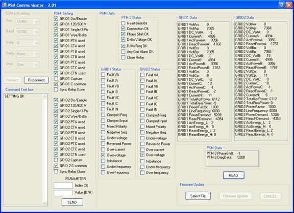
It may seem that a simulation requiring writing a complex GUI application is not very efficient. The simulation with GUI is efficient because the software engineer designing any such embedded system is usually responsible for designing/writing all additional, supporting applications, usually required for successful project completion. For example, once the printed circuit board (PCB) of the embedded system is fully populated with the parts, it has to be revived/tested, usually on a system called bed of nails. Then, if properly working, each unit usually requires calibration. These can be complex tasks requiring dedicated computing devices. With some modification, a general-purpose PC may be used. That modification is very often just adding a (PCI) board with a couple of serial ports (many embedded systems use such serial communication ports, and newer PCs are not equipped with them). Figure 4 shows such a GUI communicating with another embedded control system, a power monitoring device or power synchronizing module (PSM), via serial port.
More modern embedded systems may use network services, especially TCP/IP, and many newer MCUs/DSPs directly support Ethernet-based communications. In such cases the PC doesn’t require any additional hardware, because Ethernet-based network communication services/ports are available in every PC. Figure 3 shows such communication.
Phase 6: Debugging of the program modules
Once the program is written, the most exciting (and frustrating) phase, debugging, can start. While some programming workflows may integrate code debugging along the way, to debug all program modules thoroughly, the software engineer needs to use special tools. Simulation as described in the previous step is being used mostly for verifying a concept/algorithm of the most demanding tasks.
The final debugging usually requires use of emulators, logical analyzers and other electronic equipment. Moreover, debugging must be done on the target hardware, so this phase requires a hardware prototype to be ready for testing. Because the hardware problems of a new prototype unit cannot be excluded, this phase usually requires cooperation with the hardware designer(s).
Phase 7: Testing hardware/firmware of the embedded system
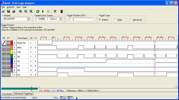
When the debugging is completed, the embedded control system requires a comprehensive testing process. This is a very important phase, which usually requires preparation of a rather complex testing plan, as many aspects and features/activities of the entire system must be tested/verified. For example, Figure 5 shows the booting sequence of the ADSP-21XX DSP digital signal processor, which was used in the embedded PSM system. Many other signal time sequences, like the serial backplane communication, A/D conversions, etc., must be similarly verified.
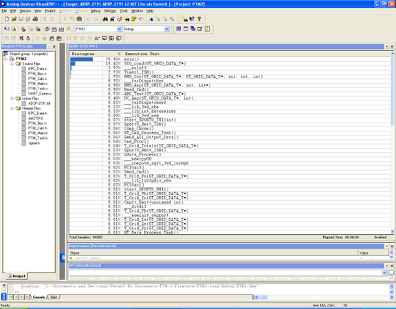
Firmware testing is not limited only to a proper functional “behavior” of the embedded system like shown in Figure 4. For example, it might be important to know how much of the computing “power” and how much of the program/data memory are still available in the embedded system processor. This is important for the eventual future firmware modifications. Figure 6 shows the tasks frequency and their duration as it had been analyzed by using the statistical profiling tool (in this case, built into the Analog Devices VisualDSP++ IDE package). A tested power transducer module (PTM-2) shows that the main() function takes almost 71% of the DSP processing capacity, though most of the time it remains in the idling state (waiting for the tasks launching). The remaining time is distributed among all remaining tasks, interrupt service routines (ISRs), etc.
Figure 7 shows a screen capture of the DSP’s internal memory utilization. It shows that roughly 50% of the program memory is still available for future needs, a thumbnail target for many applications, depending on details, of course.
A thoroughly designed embedded system should be completely “foolproof” as well, such that it would never crash even with drastic manipulation like plugging/unplugging input/output cables on the fly.
Finally, the embedded control system can be tested on the customer site. The customer may find something he/she does not like. Other findings and requirements may need further modifications/changes, filling gaps or clarifying ambiguities in the project specification. The software/firmware changes are not so bad, especially with a logical, modular software structure (like using the soft programming approach). Hardware changes are less pleasant, and often much more costly because they are usually connected with the redesign and manufacturing of a new target unit, as different parts and/or layouts may be needed. In the worst case, the project may need to return to phase 3, hardware/firmware concept design. That’s why the first two design phases, system analysis and project specification, are so extremely important.
In the last phase, as a proof that the control system is safe for intended use, certificates must be obtained, as needed, such as UL (CSA/CEN in other countries) and others. This is extremely important step, as if your module (its design) fails, you need to return to the “drawing board.” Only after obtaining all required certifications can the embedded control system be manufactured and delivered to the customer and used.
Importance of control software engineering
For decades, the profession of control engineering has been unthinkable without involving computation techniques. Analog controllers are history, successfully replaced by their digital counterparts (with heavy software involvement) long time ago. Many control engineers might be more interested in the control systems design, not only proper control system use (like tuning proportional-integral-derivative controllers, etc.). Computer science and software developer experts interested in control engineering also are interest in control software engineering. Control software engineering is the engineering field where control and computer science expert meet and collaborate.
Software engineering became a distinguished study field, and many colleges/universities offer Bachelor and Master of Science in Software Engineering (BSE, MSE) study programs. Control software engineering can be even more demanding science, with required knowledge of the control theory, electronics, digital signal processing and other areas. This article outlines the most important aspects of control software engineering and suggests there is much more to learn to become a successful control software engineer.
Peter Galan, control software engineer, retired. Edited by Mark T. Hoske, editor-in-chief, Control Engineering, WTWH Media, [email protected].
Keywords
Control software engineering, control system programming, control system design
Consider this
Do you know the seven critical phases of control software engineering?
Control Engineering magazine acknowledges the importance of control software engineering. Encourage further coverage by contacting us. Thank you in advance for your replies.