Closed-loop tuning can be used to tune a PID loop. How is it done? What data do I collect? What calculations are required? How well will it work? What problems might I run into? See “How to execute a closed-loop test in four steps” and two warnings.
Learning Objectives
- Know how to execute a closed-loop test and a relay-tuning test.
- Know how to estimate the two process parameters required to calculate proposed PID controller tuning constants and one method (of hundreds) to calculate PID controller tuning constants.
- Understand that the calculated PID controller tuning constants are only an estimate; further trimming of the tuning constants may be required to get the required PID controller performance. Also review the limitations of the closed-loop tuning method.
PID controller tuning insights
- Eighth article in the Control Engineering PID tuning spotlight series explains how to execute a closed-loop test and a relay-tuning test.
- Text and supporting figures show how to estimate the two process parameters required to calculate proposed PID controller tuning constants and one method (of hundreds) to calculate PID controller tuning constants.
- Calculated PID controller tuning constants are only an estimate; further trimming of the tuning constants may be required to get the required PID controller performance. Tips and limits of the closed-loop tuning method are covered along with two warnings.
Closed-loop tuning generally should be avoided, though if you have a loop that is already swinging, then enough information may be available to apply closed-loop tuning rules. Relay tuning is a subset of closed-loop tuning (though, strictly speaking, not all relay tuning is closed loop). Both proportional-integral-derivative (PID) tuning methods are explained.
There are three common methods used to tune control loops:
-
Open loop (PID spotlight 7)
-
Closed loop (PID spotlight 8, this article)
-
Heuristics (PID spotlights 9 and 10).
There is considerable published literature on open- and closed-loop tuning methods, and all control textbooks cover open- and closed-loop tuning. Heuristics methods are not well covered (parts 9 and 10 in this series). Each has its place in the control engineer’s toolbox. There are concepts unique to each method that will help you think critically about control loop performance.
Closed-loop tuning generally should be avoided, however, if you happen to find a loop that is already swinging, you may have all the information you need to use the closed-loop tuning rules. Open-loop tuning is generally the best choice when you have a “cheerfully start over” situation; either a new control loop or one where the process has been significantly modified. Existing control loops that just need to be trimmed up are best approached using heuristics.
Relay tuning is a subset of closed-loop tuning. It avoids the problem of pushing the process to the limits of stability by performing the test in manual mode (open loop). The method was first proposed by Karl Johan Åström and Tore Hägglund in 1984. Depending on the system, you may find this available as automated loop-tuning software, and if it isn’t, it is not difficult to write your own software. Regardless, if the process is slow enough relay tuning can be done manually.
Closed loop tuning method explanation
The closed-loop controller tuning method is done with the controller in auto mode (if you haven’t heard the term before, when a controller is in auto or cascade, it is considered to be operating in closed-loop mode.)
The method is:
-
Turn integral and derivative off. Depending on the system, you can set integral and derivative to 0, although in some systems, you must set integral to a very large number.
-
Raise the controller gain until the controller swings continuously. You may need to bump the setpoint (SP) to get a swing started.
-
When the controller is oscillating continuously write down:
-
The controller gain – this is the ultimate gain (Ku).
-
The time between process variable (PV) peaks – this is the natural period (Pn).
-
-
Calculate the tuning constants using your favorite calculation method.
How to execute a closed loop test in four steps
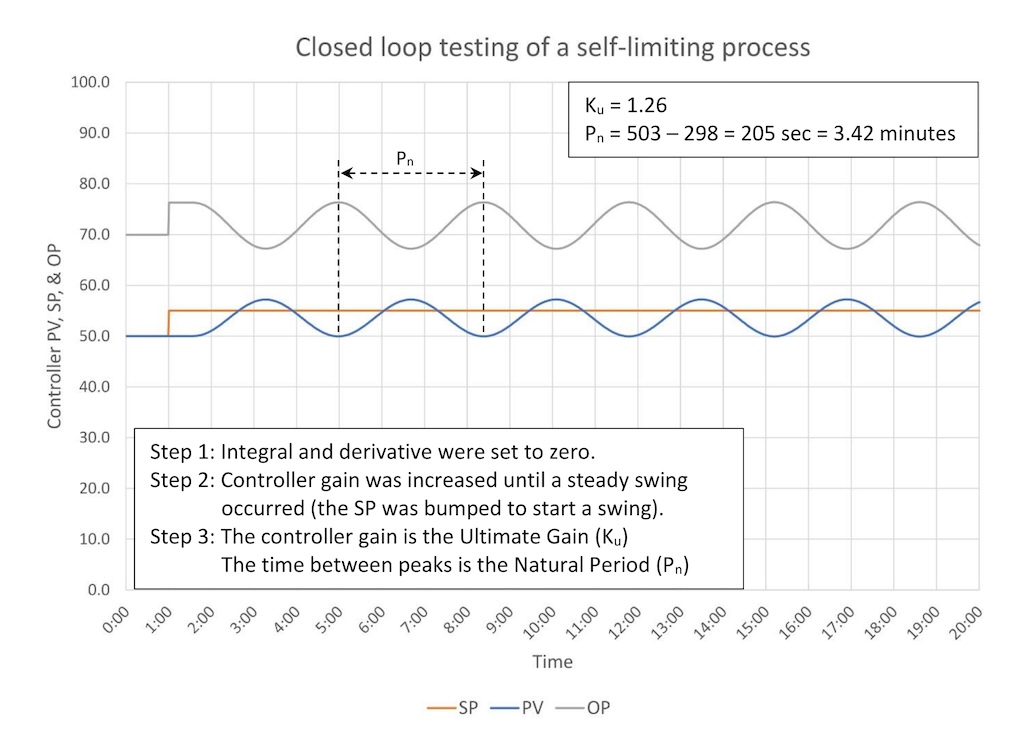
Figure 1 shows a closed-loop test for a process with a process gain of 2, three lags of 30 seconds, and a deadtime of 30 seconds.
All closed-loop tuning methods use this procedure. The only difference is how you calculate the tuning constants once you have determined the ultimate gain (Ku) and natural period (Pn).
Step 1: Remove integral and derivative.
Step 2: With the controller in auto increase controller gain until a continuous swing occurs. You may need to bump the SP a little bit to get a swing started.
Step 3: Write down Ku and Pn:
- Ku = 1.26
- Pn = 3.42 minutes
Step 4: Calculate and test.
Calculating tuning constants
There are reportedly some 400 to 500 published loop-tuning methods. I will discuss a few of the multiple methods later on, but to get you started, I will use a modified version of Ziegler-Nichols (Z-N) that aims at critically damped PID tuning.
Closed-loop tuning methods will not tell you if a process is lag dominant, moderate or deadtime dominant. If you choose to use derivative, you must verify that it improves controller performance.

For a true first order plus deadtime (FO+Dt) process these produce tuning constants that are slightly more aggressive than critically damped (a critically damped controller will get the PV to SP as fast as possible without overshoot.)
How did we do with the closed-loop test?
Table 2 shows the critically damped Z-N calculations for the process that was tested in Figure 1.

The calculated tuning constants are:
PI:
- K = 0.387
- Ti = 2.05
PID:
- K = 0.504
- Ti = 1.71
- Td = 0.41
Before we put up the performance charts, we should note that the calculated tuning constants are different from those achieved by open-loop tuning (covered in “PID spotlight, part 7: Open-loop tuning of a self-limiting process.”
Those values were:
- K = 0.63
- Ti = 1.59
- Td = 0.40 (if used)
There is a significant difference. This is because the tuning constants calculated by any given method can be quite divergent based on the assumptions built into each method. In this case, both the Simplified internal model control (IMC) and the critically damped Z-N methods are intended to provide tuning constants that will yield critically damped response to a SP change. You would think that two methods that had the same goal would provide very similar tuning constants.
Furthermore, if you were to use a loop-tuning method that is intended to achieve (let’s say) optimal disturbance rejection, you will get very different, and much more aggressive, tuning constants. There also are methods that allow you to dial in the type of controller performance you want using a performance tuning constant.
There are two points to make:
-
Regardless of the tuning method you use the calculated tuning constants may not be perfect because the assumptions embedded in the method may not match your process.
-
“Optimal” loop-tuning constants exist on a fairly broad curve. If the curve had a sharp peak, you would expect all the calculation methods to yield consistent results (and there likely wouldn’t be more than 400 loop-tuning methods).
From a practical perspective:
-
Regardless of the loop-tuning method you use, expect that you may need to trim the tuning constants to get the desired controller response.
-
You do not need to calculate tuning constants to three significant figures. Our goal is to get loop tuning done quickly to a sufficient degree of accuracy so you can work on the million other things you have to do.
Figure 2 shows the controller performance for the PI tuning constants.
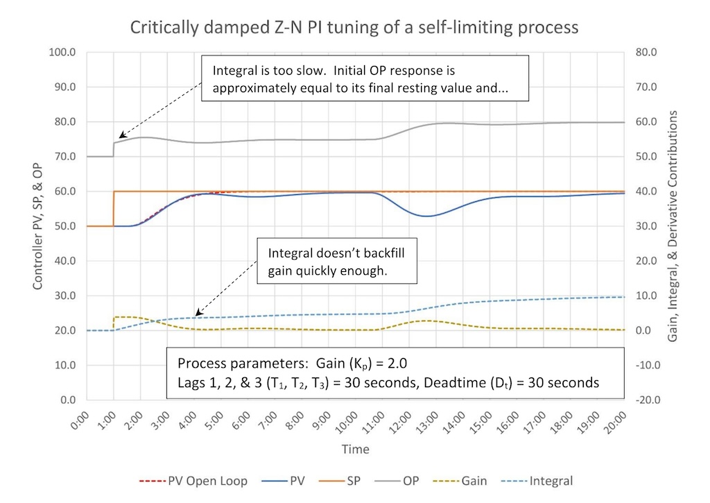
PV response to a SP change approximates open-loop response until the PV stalls without reaching SP. The response to a disturbance also shows a good initial response, but then the PV stalls before reaching SP. Based on these response characteristics, we can conclude that the integral is set too slow (see “PID spotlight, part 5: What does good and bad controller tuning look like?” under the section “What bad looks like: Integral set too slow.”
A slight reduction in the integral constant (faster integral) is recommended (1.5 is about correct).
Figure 3 shows the controller performance for the PID tuning constants.
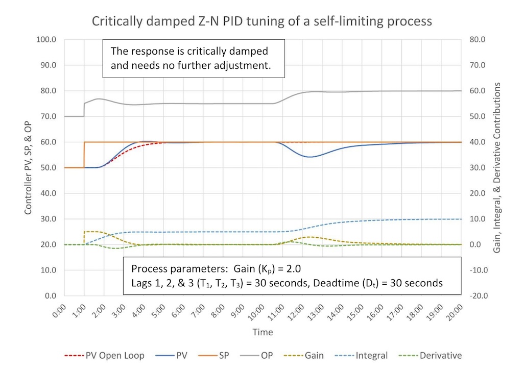
The response is critically damped for a SP change, proving that sometimes no further adjustment of the tuning constants is necessary.
Relay tuning method explained
Relay tuning is not, strictly speaking, closed-loop tuning. However, like closed-loop tuning, relay tuning induces a swing in the process and calculates an ultimate gain (Ku) and natural period (Pn), but it does this by stepping the controller output (OP) up and down in manual mode. This can be done manually, or software can be written to automate the process. As a result, relay tuning is generally quite safe.
The method is:
-
Verify the controller is lined out (no disturbances) and the PV is on SP.
-
Place the controller in manual.
-
Step the OP up ½ of the desired full OP step size.
-
When the PV moves off SP move the OP down a full step.
-
When the PV crosses the SP move the OP up a full step.
-
Repeat until the PV achieves a full steady oscillation.
-
Write down:
-
The time between PV peaks – this is the natural period (Pn).
-
The full OP step size (OPs)
-
The peak-to-valley amplitude of the PV swing (Ka).
-
-
Calculate the ultimate gain (Ku).
Ku = 4 * OPs
π * Ka
-
Calculate the tuning constants using your favorite calculation method.
Executing a relay tuning test
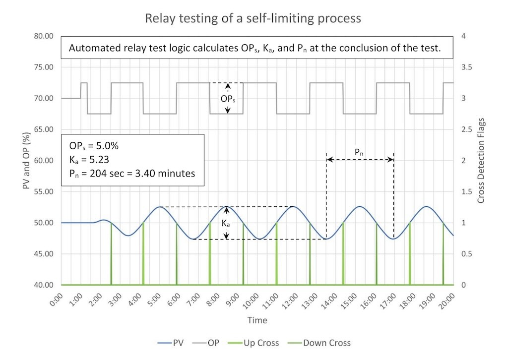
Figure 4 shows automated relay testing of a process with a process gain of 2, three lags of 30 seconds, and a deadtime of 30 seconds.
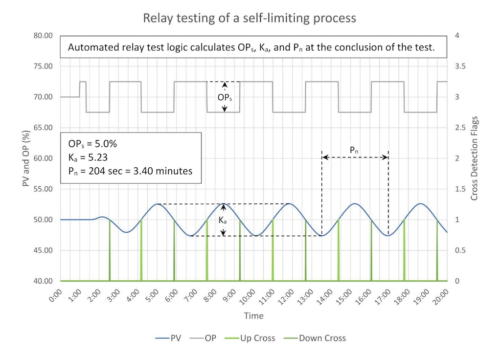
The vertical lines across the bottom are when the software detects a SP crossing. If you write your own software, trending the crossing detection will help you troubleshoot problems.
The software automatically calculates the natural period and swing amplitude. These are:
- Ka = 5.23
- Pn = 204 seconds = 3.40 minutes
The OP step size was:
- OPs = 5%
The ultimate gain is:
Ku = 4 * 5
3.14 * 5.23
Ku = 1.21
Note that when we tested this process using the closed-loop tuning method, we found an ultimate gain and natural period of:
- Ku = 1.26
- Pn = 3.42 minutes
The natural period (Pn) turned out to be within a second (204 versus 205), but the apparent ultimate gain (Ku) is a bit different (1.21 versus 1.26; a difference of ~4%). These differences are not enough to materially affect the calculated tuning constants.
Table 3 shows the critically damped Z-N calculations for the process that was tested in Figure 4.

The calculated tuning constants are:
PI:
- K = 0.363
- Ti = 2.04
PID:
- K = 0.484
- Ti = 1.70
- Td = 0.41
As expected, the tuning constants are little different from those calculated above, and we should expect that controller performance will be about the same.
Closed-loop tuning tips and a warning about closed-loop tuning
WARNING: Avoid using closed-loop tuning in a live process environment. Pushing a process to the edge of stability runs the risk that it may get away from you, which may cause an incident.
If, however, you plan to use closed-loop tuning anyway clamp the controller output some small distance above and below the current controller output (there is a hard lesson behind this advice.) Set the clamps based on how big a swing the process operator will allow.
Relay tuning tips (safer, but also with a warning)
Relay tuning is much safer than closed-loop tuning; there is little chance that a control loop will go unstable. Relay tuning can be used to tune slow loops provided you write relay testing logic that will manage the test automatically.
WARNING: You can leave it running and do something else, however, the operator must be able to stop the test automatically in the event of an upset.
Closed loop and relay tuning limitations
Slow control loops cannot be tested using the standard closed-loop method. They must be watched closely to make sure they do not go unstable. This is time consuming and tedious. It also may be difficult to tell that a controller is going unstable and once it does it will take a long time to stop the oscillation. Slow loops can be tested using relay tuning if the testing process is automated, however the test will be ruined if a disturbance occurs during the test.
Bad valves will warp the results. It may be impossible to start an oscillation at an acceptable amplitude when a valve has hysteresis and/or stiction. A bad valve will affect the estimate of ultimate gain and natural period; ultimate gain may be larger or smaller than actual, and natural period will likely be longer.
Process noise makes relay tuning difficult if not impossible. It becomes difficult to determine when the PV crosses the SP. Failure to change OP at this time will yield a false natural period.
If you walk up to a control loop that is already swinging, you can use the calculations above if the controller is swinging because it has too much controller gain. A controller with integral will swing at a period greater than the Natural Period (Papparent > Pn). If the swing is caused by excess controller gain then the apparent period will be only slightly higher than the Natural Period and can safely be used to calculate the integral and derivative tuning constants. This will be discussed in more detail in the PID spotlight on heuristic tuning, covered in parts 9 and 10 of the series.
Ed Bullerdiek is a retired control engineer with 37 years of process control experience in petroleum refining and oil production. Edited by Mark T. Hoske, editor-in-chief, Control Engineering, WTWH Media, [email protected].
KEYWORDS: Proportional-integral-derivative, PID tutorial
CONSIDER THIS
After you have executed a closed-loop test, calculated PID controller tuning constants and entered them into your PID controller, are you done?
ONLINE
PID series from Ed Bullerdiek, retired control engineer:
Part 1: Three reasons to tune control loops: Safety, profit, energy efficiency
PID spotlight, part 2: Know these 13 terms, interactions
PID spotlight, part 3: How to select one of four process responses
PID spotlight, part 4: How to balance PID control for a self-limiting process
PID spotlight, part 5: What does good and bad controller tuning look like?
PID spotlight, part 6: Deadtime? How to boost controller performance anyway
PID spotlight, part 7: Open-loop tuning of a self-limiting process
PID spotlight, part 8: Closed-loop tuning for self-limiting processes (this article)
PID spotlight, part 9: Heuristic tuning for a self-limiting process (part A on heuristic tuning)
PID spotlight, part 10: Heuristic tuning in a self-limiting process (part B on heuristic tuning)
Aug. 1 RCEP webcast available for one year: How to automate series: The mechanics of loop tuning
More on PID and advanced process control from Control Engineering
