Design standards and best practices for human-machine interfaces (HMIs) continue evolving, but simplicity and clarity never go out of style.
Whether we think about it or not, most of us, as everyday consumers, have developed opinions about how human-machine interfaces (HMIs) should look and feel. This is because we constantly use smartphones, websites and even controls on our cars, which have digital HMI interfaces. As we interact with them, we intuitively understand what is clear to comprehend and actions that are easy to perform, as well as those that are awkward or difficult.
For factory equipment and systems, specialized industrial HMIs have been around for many years. The hardware and software have improved to offer extensive options, but sometimes there are so many choices configurations can become more complex than necessary. Comprehensive standards, on the other hand, are a more recent development. However, standards are not always a clean fit for every industry, system type or preference, and they may not be specific enough for all the unique items HMIs must represent.
Industrial system and original equipment manufacturer (OEM) developers need HMIs and want them to be useful, but they may not have time or dedicated staff for creating their own extensive HMI standards and styles. The best choice for addressing this issue is often simplicity and clarity, a proven approach for delivering the best situational awareness and usability for HMIs. This article offers basic tips and best practices for planning and implementing an effective factory automation HMI.
Investigate resources
It is important to check out available resources before creating any designs from scratch. Industry documents and standards, such as ISA101 and those produced by other organizations, provide HMI design guidance. However, many of these are focused on process, petrochemical and nuclear industries.
Many HMI developers find “The High-Performance HMI Handbook” by Bill Hollifield, Dana Oliver, Ian Nimmo and Eddie Habibi to be a helpful resource. Not only does it present many best practice concepts, but it also depicts poor designs, which are all too common. But again, this book is somewhat process oriented.
Depending on the HMI platform being used, the development environment may offer standard or optional object libraries, along with other aids, for creating new projects, and these are always worth a look. Keep in mind it is very common for these library objects to require some modifications before deployment as a company standard.
Creating an effective factory HMI for a new application is often an iterative process and simplified if one starts with applicable standards or samples. A good starting point is defining building block objects.
Break it down into building blocks
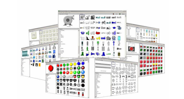
Each end user is likely to have a mix of typical industry elements, such as valves and pumps, along with specialty components — all of which must be represented on the HMI. An early step should be identifying the elements that will be used repeatedly and create a standard design for each (see Figure 1).
Not all HMI design elements relate to physical devices. HMI objects like start/stop buttons, on/off indicators, recipe values and data entry tags are logical constructs necessary for the HMI to interact with the controller, but are not necessarily depicted on any mechanical or electrical design document.
Speaking of the controller, often a programmable logic controller (PLC), the HMI must be developed in close coordination with the PLC code. If the PLC has special device alarms, or other derived values such as motor runtimes, these must be accommodated in the HMI.
Build it up with storyboards
Storyboards are a way of mapping out a creative process. They most often are associated with movies, but also can play a role in creating novels, architecture and software. In the context of developing a factory HMI, storyboards allow the designer to preplan how many screens are needed and their hierarchy so the team can review the flow before significant HMI configuration effort.
Designers may create storyboards using a text-based outline, spreadsheets, sketches or a combination of techniques (see Figure 2). Whatever method is employed, it should be flexible and allow the review team to understand and help produce a good arrangement.
The storyboards should indicate how the systems, subsystems and other detailed information are related to each other, typically in the sense of what will be shown on each screen. This arrangement depends a lot on the complexity of what is being automated, and on what building block objects must be displayed.
A very basic machine may have one or two screens to depict all operating conditions and provide a few objects for operator interaction. More complicated equipment will have more screens, including some that provide detailed operator-entry values, historized data trending, alarm/event logs and derived performance and diagnostic information.
Once factory automation reaches a certain level of complexity, it may be useful to introduce an HMI organization concept of levels such as:
- Level 1 dashboards: Provide summary “at a glance” operating information
- Level 2 typical control: Streamlined operating screens, provide the essential monitoring and control options
- Level 3 detailed control: Detailed operating screens, with more options than Level 2
- Level 4 specific control: Very detailed popup, configuration, or diagnostics screens, not regularly used.
During the storyboarding process, remember team members include not just programmers, but also those from other engineering disciplines, along with operators, maintenance members and management. Each member should contribute corresponding to their role.
Five ways to define an HMI’s style
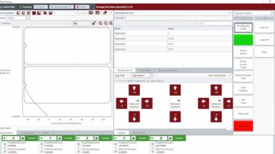
The style for an HMI encompasses many looks, feel and functionality aspects. While current “high-performance” HMI concepts call for minimized colors and very simple objects, users must adopt what is suitable for their specific application (see Figure 3). Considerations for creating an HMI style guide include navigation and availability, color choices, data text definitions, simple graphics and usability.
1. Navigation and availability. Common sense indicates the most important controls, typically start and stop commands, as well as navigation buttons, should always be easily available. A common way to do this is by reserving a portion of every screen for these controls.
Popups are smaller windowed screens appearing in front of a full display screen, usually used briefly for viewing and/or entering very specific information and then dismissed. Sometimes it is helpful to allow a popup to persist, such as for a proportional-integral-derivative (PID) tuning faceplate. However, while popups may be useful for infrequent detailed tasks, they can be a distraction for normal operation, consume space on the display and should often be avoided.
Password protection security should be applied as needed, but judiciously to avoid locking down a system and impeding operators. It is often useful to consolidate machine tuning parameters on a single password-protected screen.
2. Be careful with color. Colors are used for backgrounds, fonts, static elements and animated objects, but they can be a debated HMI topic. Most standards recommend light grey backgrounds and greyscale objects, with colors reserved for abnormalities. This provides easy visibility and guides users to what is important. However, an industry or equipment may dictate the use of color. Power industries often use red for energized (danger) and green for de-energized (safe). If an equipment item has three color-coded subsystems, perhaps it makes sense to include those colors on the title bar for easy recognition.
Also, avoid relying only on animated color coding of objects. Where possible, it is better to provide a secondary supplementary symbol indication of a state or condition.
3. Defining text data. Style also extends into what fonts are used and how text is capitalized. Plan on defining just a few fonts to cover the necessary scenarios. Reserve larger/bolder versions for titles and important things, and smaller types for details. Make it clear which values are display-only, and what can be operator-entered. Include engineering units and allowable ranges.
4. Streamline graphics for simplicity. A key benefit of digital HMIs is the ability to present graphical images and icons that can be recognized by users without requiring reading or possible misunderstanding due to language barriers. However, that doesn’t mean the graphics should be detailed engineering drawings, complex photographs or anything animated.
Instead, the contemporary best practice is provide simplified iconic graphics where possible. Constant animation may be useful in limited cases, but it consumes processing resources and is usually considered a distraction.
While bitmap-type images are discouraged, there are many good reasons to include them in factory automation. Designers can include images of equipment and parts with arrows, for instance, to clearly indicate to users where trouble is occurring.
5. Usability first. Investigate other advanced features that help operators do their job. Don’t just show the current level of a vessel, but instead make the level available as a trend so the operator can understand how the system has recently operated. Even better, embed critical indicated values as mini trends right on a screen.
A similar concept applies to alarms. For most systems, it is important to indicate currently active alarms. A detailed historical alarm/event logs with date/time stamps can assist troubleshooting efforts by letting users review how an issue developed.
Situational awareness is the goal
The concept of situational awareness developed out of military theory and more recently, the aviation industry, but it is applicable for industrial factory automation designs. The end goal for the HMI portion of an automated system is providing all relevant information so users can understand what is happening and know what action is required.
Large engineering firms or process facilities may have significant resources available to develop their HMIs. However, smaller organizations, system integrators and OEMs can take advantage of the latest design concepts. A design process considering all the preceding topics, and involving the key personnel as development begins, will ensure creation of a clean and useful HMI experience.
Bill Dehner has spent the majority of his 14-year engineering career designing and installing industrial control systems for the oil and gas, power and package handling industries. He has a BSEE with an associate degree in avionics from the USAF and is currently working for AutomationDirect as a technical marketing engineer.
This article appears in the Applied Automation supplement for Control Engineering and Plant Engineering.