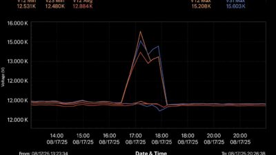
This study evaluates harmonic mitigation techniques in medium-voltage systems, looking at a measured plus modeled evaluation of the most common mitigation approaches (passive filters and 18- and 24-pulse VFD configurations) against IEEE 519 voltage distortion limits.

Power quality, drives and harmonics insights
- Understand how MV VFDs introduce harmonics and how those harmonics impact voltage quality, equipment reliability and system losses.
- Compare the harmonic mitigation performance of 12-pulse, 18-pulse and 24-pulse drives.
- Evaluate system harmonic levels and verify compliance with IEEE 519 using power system analysis tools.
Power electronic converters are widely used in modern industrial facilities to improve energy efficiency and process control. While these technologies offer significant operational benefits, they also introduce harmonic distortion that results from their nonlinear current draw. Harmonic currents propagate through electrical networks, thereby degrading voltage quality, increasing losses and reducing equipment reliability.
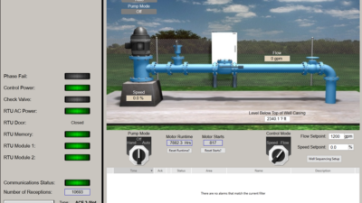
Water and wastewater treatment plants are particularly affected because they rely heavily on variable frequency drives (VFDs) to control large pumping systems. These facilities often operate continuously and include sensitive electrical equipment, thus making power quality a critical design and operational consideration. Therefore, harmonic analysis and mitigation are essential for ensuring stable operation and compliance with power quality standards. Figure 1 summarizes common harmonic challenges in wastewater treatment facilities and typical mitigation approaches.

Harmonic impact on power quality
Harmonic distortion is primarily produced by nonlinear loads, such as VFD rectifier front ends. These devices draw non‑sinusoidal currents that interact with system impedance, subsequently producing voltage distortion at multiple locations within the electrical distribution system. Excessive harmonic levels increase root mean square (RMS) current, resulting in higher copper losses, while also introducing frequency-dependent eddy currents, stray flux and core losses in transformers (thus leading to overheating, accelerated insulation aging, nuisance tripping of protective devices and reduced equipment life).
IEEE 519 establishes recommended limits for voltage and current harmonic distortion to minimize these adverse effects. For MV systems, total harmonic distortion (THD) is generally limited to 5%. Exceeding this threshold increases thermal stress on equipment and can compromise the reliable operation of sensitive loads (Figure 1).
Harmonic characteristics and mitigation In variable frequency drives
VFDs improve motor efficiency by converting fixed frequency AC power into a variable‑frequency output. However, the rectifier stage of a VFD generates characteristic harmonic currents whose spectrum depends on the converter pulse number. The dominant harmonic orders follow the general relationship presented in the following equation:
Where:
- h = harmonic order
- p = pulse number of the converter
- n = integer (1,2,3…)
This concept is fundamental in the field of power electronics and in power quality standards such as IEEE 519.
Higher‑pulse configurations—such as 12‑pulse, 18‑pulse and 24‑pulse drives—use phase‑shifting transformers to cancel characteristic harmonics. Increasing the pulse number reduces low‑order harmonic content and improves overall power quality, though at the cost of increased system complexity, footprint and capital expense.
Harmonic analysis methodology
The harmonic performance of the electrical distribution system was evaluated using a staged analysis approach in ETAP. The objective was to quantify harmonic distortion under different VFD configurations while maintaining consistent operating conditions.
In the first stage, the system modeled 12-pulse VFDs to establish baseline harmonic performance and to determine compliance with IEEE 519 limits. In the second stage, the VFDs were reconfigured as 18‑pulse drives and harmonic distortion levels were reassessed. In the third stage, the system was modeled with 24‑pulse VFDs to evaluate further harmonic reduction. This approach enabled direct comparison of mitigation effectiveness without introducing changes to system loading or topology.
Water pump station system description
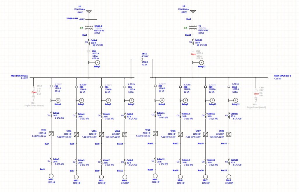
The water pump station evaluated in this study operates several MV VFDs at 4,160 volts (V) to control large pumping systems. The VFD drives 2,250 hp motors that move water from one canal to the next.
Figure 2 shows a portion of the electrical system modeled in ETAP. Two utility sources (operating at 69 kilovolts [kV]) supply power to two main switchgear buses (SWGR Bus‑A and SWGR Bus‑B) through 21 MVA step‑down transformers. The switchgear buses operate at 4,160 V and are interconnected by a tie breaker, with the bus tie normally open, allowing either of the two utility sources to supply the system during contingency conditions.
Maintaining a consistent MV level across major loads simplifies system design and improves distribution efficiency by minimizing additional voltage transformation stages (Figure 2).
Outcomes of harmonic analysis, mitigation
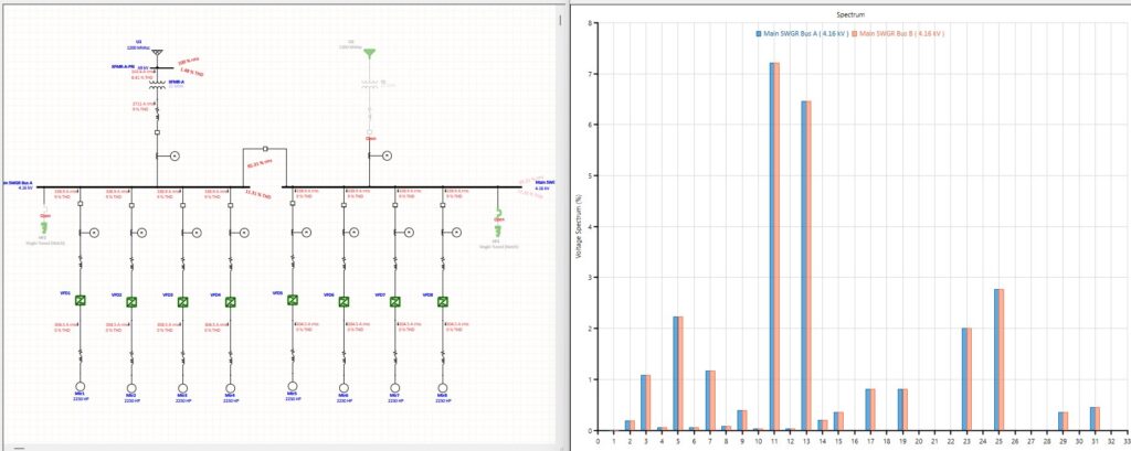
The baseline harmonic analysis showed a voltage THD of 11.31% at the main switchgear buses when 12‑pulse VFDs were used, as illustrated in Figure 3. This value exceeds the IEEE 519 recommended limit of 5%, confirming the need for harmonic mitigation.


Harmonic mitigation method 1: Passive filter installation at switchgear buses
One mitigation approach involved installing passive harmonic filters at SWGR Bus‑A and SWGR Bus‑B. Filter parameters were determined based on the harmonic voltage spectrum and system impedance, as shown in Figure 4 and Figure 5.
After filter installation, voltage THD was reduced from 11.31% to approximately 1.79%, and individual harmonic distortion (IHD) values were reduced to less than 3%, as shown in Figure 6. These results demonstrate that properly designed and located passive filters can effectively mitigate harmonic distortion and achieve IEEE 519 compliance. However, passive filters introduce additional equipment, require installation space and must be carefully coordinated to avoid resonance or undesirable voltage profile impacts.

Active harmonic filters (AHFs) were not evaluated as part of this study. Active filters can dynamically mitigate harmonic orders and are effective in systems with VFD loads; however, in MV applications, AHFs are less common because of their complexity and higher upfront cost. For the harmonic analysis performed and identified, passive filters provide a practical and effective approach for achieving IEEE 519 compliance.
Method 2: Implementation of 18-pulse VFDs
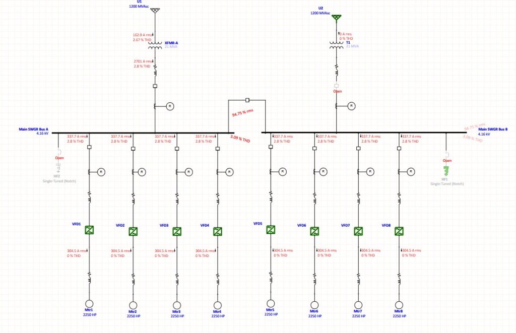
Replacing the 12‑pulse drives with 18‑pulse VFDs significantly reduced harmonic distortion without the need for additional filtering equipment. The analysis showed that voltage THD decreased to approximately 3.09%, while IHD values were reduced to about 2.8%, as illustrated in Figure 7. This configuration met IEEE 519 limits and demonstrated that higher‑pulse VFDs can provide effective harmonic mitigation through inherent harmonic cancellation.
Method 3 – Implementation of 24-pulse VFDs
Further mitigation was evaluated using 24‑pulse VFDs. Increasing the pulse number enhanced harmonic cancellation and reduced distortion levels even further. The analysis showed a voltage THD of approximately 2.76% and IHD values of 0.863%, as shown in Figure 8, which are well below IEEE 519 limits. While 24‑pulse drives provide superior harmonic performance, their increased cost, size and transformer requirements must be considered during system design. The increased number of rectifier bridges and the larger phase‑shifting transformer required for a 24‑pulse configuration result in greater system size, complexity and overall installation cost.
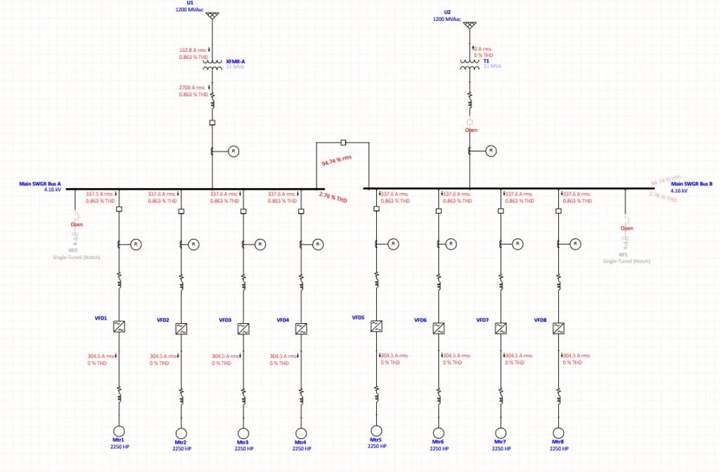
From a practical cost‑comparison standpoint, 24‑pulse VFDs typically represent a notable premium compared to 12‑pulse systems. In many industrial applications, the total installed cost of a 24‑pulse drive can be 1.5 to 2 times higher than that of a comparable 12‑pulse VFD, depending on voltage class, enclosure requirements and manufacturer‑specific design. Including this order‑of‑magnitude comparison helps highlight the balance between improved harmonic mitigation and the higher capital investment required (Figure 8).
Equipment, operational impacts of harmonics
Harmonic distortion imposes both thermal and mechanical stress on electrical equipment. Increased RMS current caused by harmonics leads to higher conductor losses and elevated operating temperatures, with transformers being particularly affected because of increased eddy current losses that accelerate insulation aging and reduce service life.
Harmonic flux components can also induce mechanical vibrations in transformer cores and windings, thereby contributing to structural fatigue over time. In addition, sensitive electronic equipment—such as control panels, automation systems and instrumentation—can experience malfunction or premature failure owing to voltage distortion and electromagnetic interference.
Motors are similarly impacted, as harmonics cause additional heating through increased RMS current and stray load losses, thus reducing efficiency and accelerating insulation degradation. Torque pulsations that result from harmonic distortion can lead to mechanical vibration, acoustic noise and uneven bearing wear; in severe cases, the pulsations may cause nuisance tripping of protective devices or premature motor failure. For critical applications, appropriate harmonic mitigation measures—such as filtering and proper system design—are essential for maintaining equipment performance and reliability.
Filters or higher-pulse VFD configurations help
This study evaluated harmonic mitigation techniques of the water pumping station electrical distribution system using simulations. The baseline configuration with 12‑pulse VFDs produced a voltage THD of 11.31%, which exceeds IEEE 519 limits.
Three mitigation approaches were assessed: passive harmonic filters, 18‑pulse VFDs and 24‑pulse VFDs. Passive filters reduced THD to 1.79%, while 18‑pulse and 24‑pulse VFDs reduced THD to 3.09% and 2.76%, respectively. All three approaches achieved IEEE 519 compliance.
The results demonstrate that harmonic mitigation can be effectively achieved through either strategically placed passive filters or higher‑pulse VFD configurations. Selection of the optimal approach should consider system performance requirements, available space and overall project cost. Proper harmonic analysis and mitigation are essential for improving power quality, ensuring equipment reliability and supporting the long‑term operation of industrial wastewater treatment facilities.
Chaitanya Thalluri, CDM Smith, Chennai, Tamil Nadu, is an electrical engineer, and Viatcheslav Taleiko, CDM Smith, Burnaby, British Columbia, Canada, is a professional engineer. Edited by Mark T. Hoske, editor-in-chief, Control Engineering, WTWH Media, [email protected].
You also might like
See related article from CDM Smith.
https://www.controleng.com/power-quality-fundamentals-vfd-impacts/