Power quality can significantly impact facility and utility electrical systems, including causing equipment outages and failures. This article describes the basics of power quality, identifies the types of disturbances and how to monitor and mitigate them, and explains how VFDs can affect power quality.
Power quality, drives and harmonics insights
- Understand how “power quality” is defined.
- Learn about the different types of power quality disturbances and problems.
- Recognize the effects of motors (and VFDs) on power quality.
What is power quality? “Power quality” is a universal term used by the industry to describe disturbances, disruptions, and other phenomena that negatively impact power systems within utility grid and user facilities.
Power quality describes how well the voltage magnitude, frequency, and waveform characteristics of an electrical supply meet established standards for a given application or piece of equipment. Power quality is a critical factor affecting the reliability, performance, and safety of a facility’s electrical systems. Poor power quality can have significant negative impacts on the facility and its electrical system, such as causing equipment malfunctions, process downtime, and safety hazards, as well as reducing equipment life expectancy and increasing operational and maintenance costs.
Power quality is a two-way street. Because a facility’s electrical system is interconnected with that of the electric utility, both systems can affect (that is, damage or improve) power quality. The utility is primarily responsible for providing a stable incoming voltage waveform, while the facility is responsible for drawing current in a reasonably non-distorted waveform that is roughly in phase with the utility’s waveform.
Ideally, a utility provides a facility with an incoming connection via a set of three (if you have three-phase service) feeders, each with a 60.0-hertz [Hz] pure sine wave at 100.0% of the facility’s rated voltage—often rated at 208 V, 480 V, 4160 V, 12.47 kV, or other voltages—which never deviates from the 60.0 Hz or 100.0% voltage mark. In actuality, deviations are frequent (and expected). Deviations in utility supply voltage and frequency can result from sudden load changes on the grid, variations in customer demand, or failures of generation and distribution equipment. In the United States, utility voltage tolerance is defined by ANSI/NEMA C84.1, American National Standard for Electric Power Systems and Equipment – Voltage Ratings (60 Hz). This standard specifies a voltage tolerance of ±5% at the point of connection between the supplier and consumer, and ±10% at utilization equipment within the facility (e.g., in a 480 V system, the tolerance at the service entrance would be 456 V to 504 V and 432 V to 528 V at the equipment). The nominal system frequency is 60.0 Hz, with an allowable tolerance of ±0.5% (59.7 Hz to 60.3 Hz).
Similarly, a facility is not likely to draw an ideal current waveform from the utility. In modern electrical systems, there are many loads that can negatively impact power quality. Common contributors include electronic and nonlinear loads—such as computers, servers, LED lighting drivers, and variable frequency drives (VFDs)—all of which draw current with an imperfect waveform (containing harmonics). Inductive loads like motors tend to draw current that is out of phase with the utility’s voltage (described as having a low power factor), which can subsequently decrease the voltage at and near the motor location. The starting of large motors or other loads can also have negative impacts on power quality. While individual utilities typically set their own limits for a customer’s power factor, harmonics limits are established by IEEE 519, IEEE Standard for Harmonic Control in Electric Power Systems.
Types of power quality issues or disturbances
Many disturbances and contributing factors can affect power quality within electrical systems. These include the following:
- Sags/dips – Voltage sags (also referred to as dips) are defined (by IEEE 1159, IEEE Recommended Practice for Monitoring Electric Power Quality) as temporary (between 0.0083 seconds and 60 seconds) decreases of electrical system voltage to between 10% and 90% of the system’s nominal voltage. Sags can be caused by a number of reasons, including faults on the electrical system (on either the utility side or the facility side) or the switching/starting of large motors or loads. Sags are sometimes observed in the form of flickering/dimming lights within buildings.
- Swells/overvoltage – Voltage swells (as defined by IEEE 1159) are increases in the electrical system voltage to over 110% of the nominal voltage for transient periods between 0.0083 seconds and 60 seconds. Swells can be caused by certain types of faults (depending on the electrical system configuration) as well as large load switching.
Short-duration overvoltage events (which rise to thousands of volts above a facility’s nominal voltage) are known as spikes, surges, or transients. These events are typically caused by load switching, lightning strikes, surges, or faults.
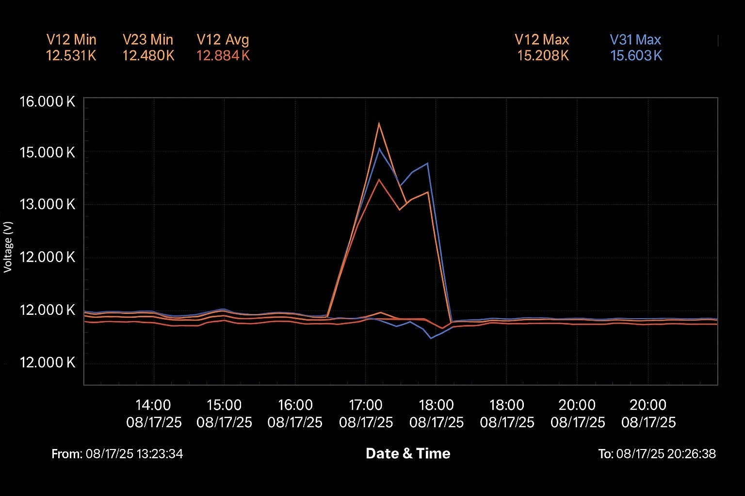
Long-duration swells, often called “sustained overvoltages,” may indicate a problem with the utility source (such as a faulty voltage regulator or tap changer). Figure 1 shows an example of a sustained overvoltage on a medium-voltage utility service.
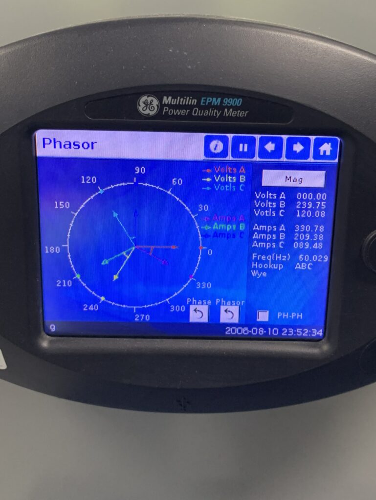
- Imbalance – Imbalance occurs in three-phase systems and refers to disturbances in both the magnitude and phase of the voltage (or current) waveforms from their normal values (where each phase should be separated by exactly 120 degrees from the other phases). These disturbances are caused by unequal load distribution or fault events. Imbalance causes “negative sequence” components in the voltage or current waveforms. An analogy for understanding negative sequence voltage components is to imagine the effect of a small generator connected to the system is spinning in the wrong direction. Imbalanced conditions can cause excessive heating for motors and electronic components connected to the electrical system.
- Power factor – Power factor is a measurement of the amount of power flowing through the electrical system that is devoted to useful work. In alternating current (AC) power systems, when the voltage and current waveforms are perfectly aligned, 100% of the power is devoted to useful work (this is described as 100% or unity power factor). When the current waveform leads the voltage waveform, it is referred to as leading power factor (typically caused by capacitive type loads). Similarly, when the current waveform lags behind the voltage waveform, the power factor is considered to be lagging (typically caused by motors, transformers, and other inductive type loads).
- In industrial applications, power factor is commonly less than 1, owing to inductive loads such as motors and transformers (Figure 2 provides an example of an industrial power system with an ~86% or 0.86 power factor). When a portion of the power flowing through the electrical system is not used to do real work, the overall current within the system increases while the real power transmitted stays the same, thus decreasing the efficiency of the electrical system by increasing the heating in conductors throughout the system. Additionally, a lower power factor increases the voltage drop and thereby decreases the voltage within the system. Utilities may impose penalties on customers with power factor values below established limits.
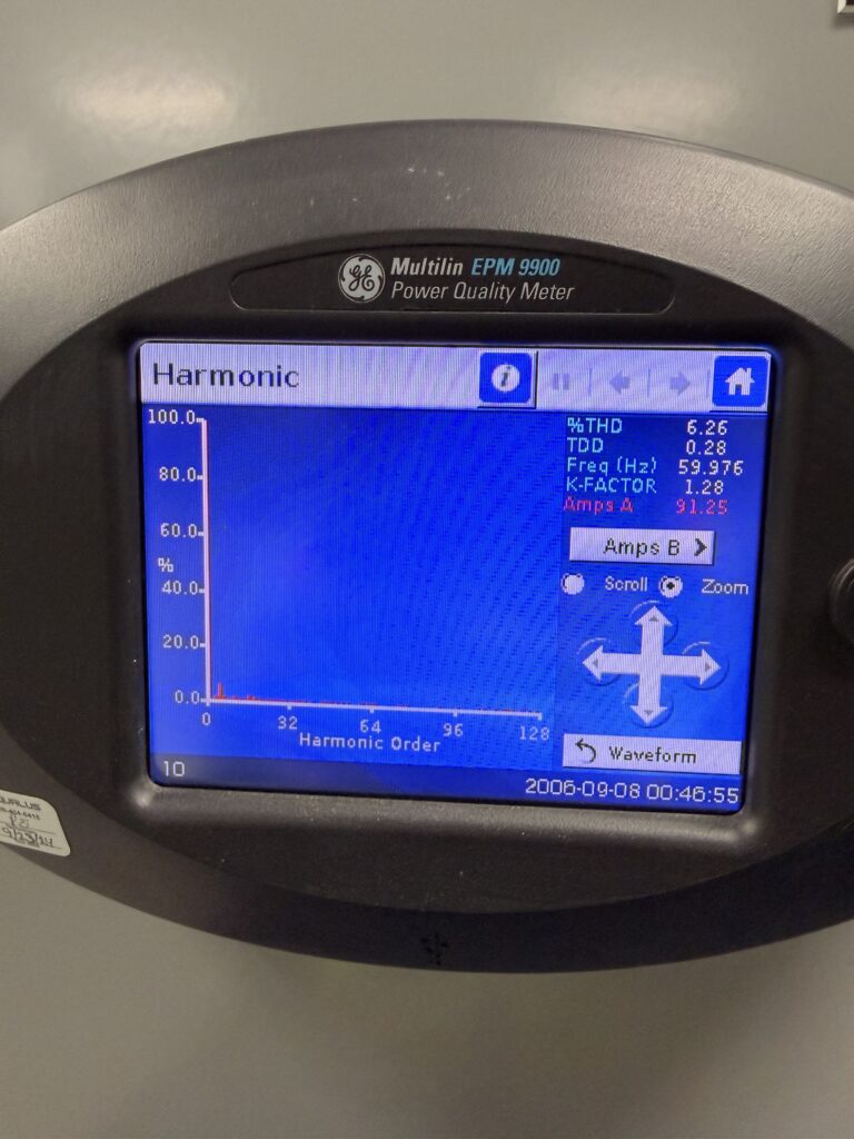
- Harmonics – Harmonics are additional currents (or voltages) within an electrical system that are at frequencies above (at exact multiples of) the nominal frequency (60 Hz in the United States) and which are superimposed on the normal nominal frequency waveform. Similar to low power factor loads, these harmonics generally do not do useful work and contribute to excess heating of components, which can result in equipment damage. Harmonics can also cause nuisance tripping of circuit breakers at high enough levels. Figure 3 contains an example power quality monitor showing harmonics within an industrial power system.
Identifying power quality issues
Power quality issues can be identified through several observable symptoms, including equipment overheating, frequent or premature equipment failures, and operational disruptions. These disruptions may present as nuisance tripping of circuit breakers, often caused by harmonics or voltage disturbances. In some facilities, low utility voltage conditions can prevent equipment from starting properly or cause circuit breakers to trip. As voltage drops, current increases, which can overload equipment and protective devices, leading to additional interruptions. In some cases, utilities may notify customers when power quality issues are detected, particularly those related to low power factor or excessive harmonic distortion.
Power quality monitoring
The most common first step in identifying and addressing power quality issues is to monitor and identify the exact power quality issue.
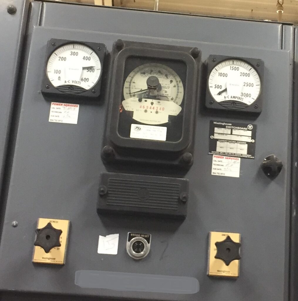
- Meter types/features – Typical analog meters present in electrical equipment are not particularly helpful while analyzing or monitoring power quality. Modern digital power quality meters use electronics to record the voltage and current waveforms within power systems and to detect all types of power quality problems. Figure 4 contains an example of an analog type power monitor installed in a 480V industrial switchgear.
- Each meter has a different feature set that will clearly define the types of disturbances it is designed to record. Most meters will identify the “continuous” type power quality problems, such as low power factor or high voltage imbalance. More advanced meters will have logging capability to record transient disturbances, such as sags and swells. The most advanced meters are capable of monitoring harmonics and recording the actual waveforms of individual disturbances at resolutions of ≥512 samples per cycle.
- Networking – When installing power quality meters, consider how the data will eventually be collected. The recorded data should be monitored by a facility-wide system to maximize the value of power quality monitors and thereby aid in trending and quickly identifying problems. For long-term problems such as power factor, imbalance, or harmonics, it can be cost effective to connect power quality meters to the facility’s supervisory control and data acquisition (SCADA) system and to record/trend data within that SCADA system.
- To identify transient/random events and record data from a network of meters, a dedicated centralized power monitoring network/system may be required.
- Common metering problems – One of the most common issues with power quality meter installation is incorrect selection/wiring of the current and potential transformers (CTs and PTs, respectively). Most power quality meters use instrument transformers to reduce the high current and high voltage levels within the electrical system to levels that are safe for connecting to the meter (typically 120 V and 5 A nominal). The ratio of the instrument transformers must be correctly entered into the power quality meter to ensure that the readings and recordings on the meter are scaled accurately to represent the actual values within the electrical system.
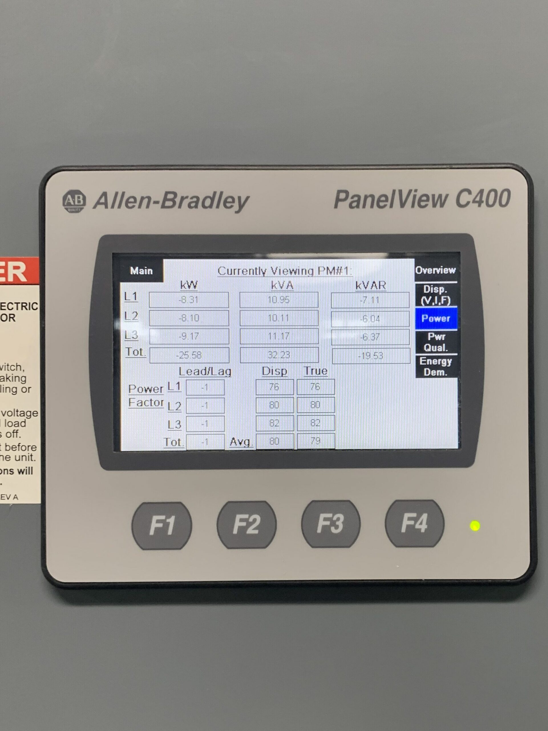
Additionally, the polarity and wiring of the instrument transformers can affect the accuracy of the meter. The polarity of the CT connections, and connection to the correct phase input (A, B, or C), is essential for the meter to correctly calculate power, power factor, harmonics, etc. If the instrument transformers are incorrectly connected to the power quality monitor, the calculated values may be incorrect (Figure 5 contains an example power quality monitor with incorrect power readings due to incorrect connections).
Power quality improvements and disturbance mitigation
As discussed above, power quality issues can result in equipment failures, operational disruptions, safety hazards, and reduced system efficiency. Accordingly, power quality improvement and disturbance mitigation measures should be considered during the system design and post-installation phases. Common methods used to detect and mitigate various power quality issues include power quality monitoring (to detect issues within electrical systems), voltage regulators (for longer duration low-voltage conditions), capacitor banks (to correct significant power factor problems and/or increase system voltage), harmonic filters (to mitigate unacceptable harmonic levels), and uninterruptible power supplies (UPSs).
UPSs can be particularly helpful in mitigating power quality issues for sensitive equipment. Some UPSs (called “double conversion” type) fully rectify the incoming AC power and generate their own independent AC output. Power quality problems such as voltage sags, swells, imbalances, and harmonics are thus not transmitted through the UPS; therefore, equipment powered from the UPS is completely isolated from external power quality disturbances (including short power interruptions). UPSs are commonly used to supply sensitive computers and lab equipment.
The effects of motors on power quality
In industrial applications, motor loads are widely used to provide motive power for pumps, conveyors, and all types of machines. Because of their inherently inductive nature, as well as their frequent motor starting and stopping and the use of VFDs, motor loads can have a significant impact on power quality. These impacts should be evaluated by both the electrical design engineer and end user. If necessary, appropriate mitigation measures should be implemented to address any power quality issues.
Motor starting
Motor starting, especially for large motors, is one of the primary causes of voltage sags within facility electrical systems. When motors start directly connected to the electrical system, they draw significantly more current than during use in continuous operation (often greater than six times the normal continuous current). Even motors as small as 50 horsepower (hp) can sometimes cause unacceptable voltage sags if started directly.
The impacts of motor starting on the electrical system can be limited by using soft starting devices (both electronic or reduced-voltage autotransformer types are commonly used) or by operating the motor on a variable frequency drive.
Variable frequency drives
VFDs, commonly referred to as drives, allow for control of motor speed and improve process efficiency and operational flexibility. While motors operated by VFDs remain inductive and draw current at a lower power factor, the VFD input typically operates at a near unity power factor. As a result, VFDs often improve overall system power factor, increase electrical efficiency, and help maintain compliance with utility requirements.
VFD harmonics
Although VFDs improve power factor, they introduce harmonic distortion through their use of power electronics to convert AC to DC and then back to variable frequency AC to adjust the motor speed. Without proper system evaluation and proper VFD selection, harmonics in systems with large quantities of VFDs can easily exceed the acceptable standards defined by IEEE 519.
From a power quality perspective, VFDs differ primarily in their converter (rectifier) section configuration:
- 6 Pulse VFDs: Use six diodes in the converter section. It is the simplest and most cost effective method, but generates high harmonic distortion.
- 18 Pulse VFDs: Use three sets of six diodes and a phase shifting transformer to reduce harmonics; these are effective but require additional space and have a higher initial cost.
- Active Front End (AFE) VFDs: Use active power electronics in the converter section to mimic a normal waveform on the input side of the VFD, significantly reducing harmonics; these are compact and more efficient than 18-pulse VFDs, but are more costly than 6-pulse VFDs.
Harmonic filtering
When harmonic levels exceed the acceptable limits, harmonic filters can be installed either at individual VFDs or in upstream distribution equipment to remove harmonics from the system.
Harmonic filters can either be active or passive type. Active harmonic filters use active power electronics (similar to the converter section of an AFE VFD) to cancel out harmonics generated by external loads. Passive filters use specially selected combinations of capacitors and inductors to trap harmonics generated by other loads within the system.
Taha Mohammed, PE, and Ian Smith, PE, are electrical engineers with CDM Smith, Fairfax, Virginia Edited by Mark T. Hoske, editor-in-chief, Control Engineering, WTWH Media, [email protected].
Keywords
Industrial power quality, harmonics, VFD power quality
Consider this
Are you addressing power quality challenges or paying long-term penalties.
You also might like
Search on CDM Smith or power quality or drives at www.controleng.com for more articles.