From fragmented to harmonized: Industrial human-machine interfaces (HMI) can become cluttered and inconsistent over time, posing risks to operational efficiency, reliability and safety. A five-phase process for HMI modernization begins with discovery and ends with measurable results.

HMI design upgrade insights
- Diagnose common patterns in legacy HMI systems—including inconsistent graphics, nonstandard tag naming, duplicate mappings and poor documentation—and explain how these conditions increase operator cognitive load, slow diagnostics and elevate operational risk.
- Apply a five-phase modernization framework to plan an HMI harmonization effort that prioritizes high-risk areas and delivers improvements beyond cosmetic screen cleanup.
- Specify the core standardization building blocks that enable scalable HMI performance, including standardized symbol templates, dynamic faceplates, a hierarchical tag naming convention, multi-level navigation and alarm/diagnostic visibility to support maintainability and future expansion.
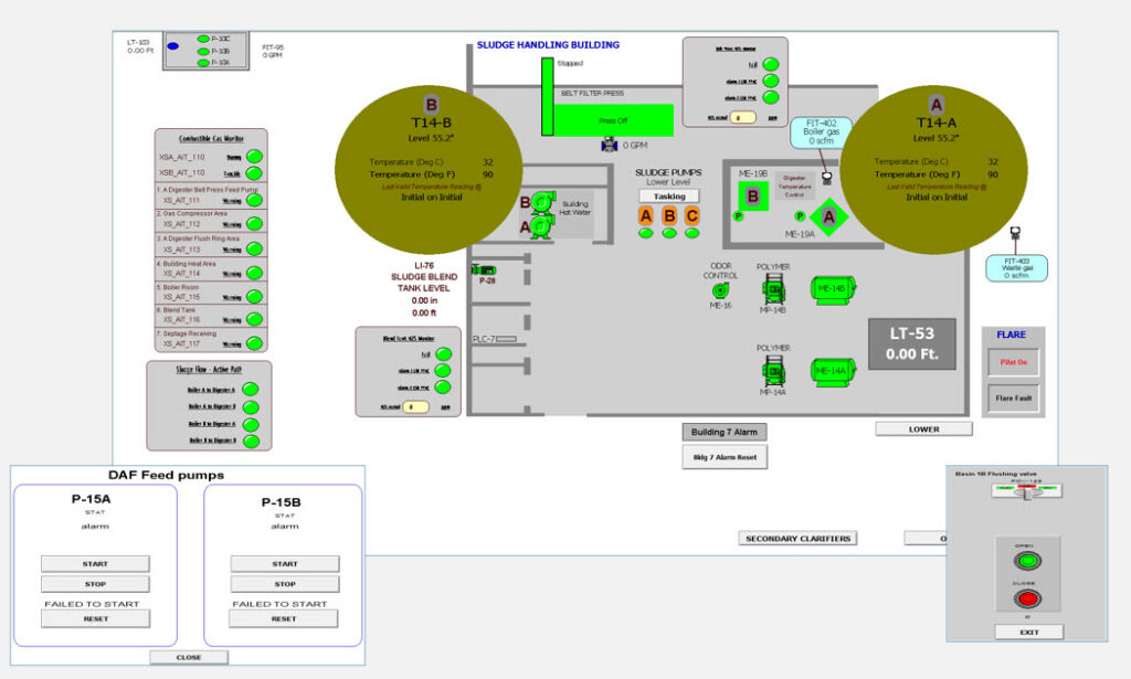
Industrial human-machine interfaces (HMI) do not remain pristine after commissioning because changes eventually take a toll on the system—incremental updates, new equipment additions and changes to operational requirements occur during years of system growth and development. Most legacy HMIs reflect this gradual evolution. Inconsistent graphical components, varying tag naming conventions, and even basic components used within legacy HMIs (such as digital alarms, analog indicators, motor objects and valve objects) do not have common templates. If left unchecked, these inconsistencies can negatively affect usability, process reliability, operation efficiency and plant safety (Figure 1).
As seasoned staff leave, unwritten rules start to fade. Training new staff is more time-intensive than in the past because every system feels different. Maintenance teams face steeper learning curves, and engineering changes carry a higher risk of unintended consequences. As a result, the operator experience makes diagnostics difficult, slows down responses and increases the cognitive load in the control room.
Taking structured approach to transforming a fragmented HMI helps create a streamlined harmonized system. Standardized clear visuals unify HMI design and help teams respond faster. Furthermore, maintenance is streamlined across sites. Future upgrades are seamless when the groundwork stays consistent. Though the modernization scope described herein is limited to the HMI layer, a clear understanding of the existing PLC environment is still required. PLC data structures and tag definitions must be reviewed to enable effective and sustainable HMI standardization, even if there are no PLC logic changes to implement.
Taking a five-phased approach to HMI harmonization can improve usability, strengthen maintainability, enhance diagnostic capability and create a scalable foundation for future expansion.
1. Discovery phase: Mapping the maze
A successful transformation starts with a comprehensive audit of the existing HMI and control system infrastructure. Without clear documentation or standards, discovery becomes one of the most critical steps. Reverse-engineering/auditing is time-consuming, but it uncovers underlying logic and identifies improvement opportunities, thereby revealing how the HMI works.
Users respond to the visual presentation on screen. Inconsistent pop-up displays—filled with mismatched icons, different styles and colors—become redundant. Although operators acclimate, such layouts fail to make tasks easier, clearer and faster. The user experience is fragmented when HMI components are created independently without standardized templates.
Tag management often hides problems. Over time, plant upgrades, process changes and expansions introduce hundreds of new tags into PLCs and HMI databases. Without a consistent naming structure and disciplined address management, engineering tasks done during upgrades can become much more demanding, thereby complicating future expansions and making troubleshooting slower and prone to errors.
An important outcome of the discovery phase is prioritizing what matters most. Some flaws carry more weight than others because risk is not spread evenly. Screens that support critical processes or alarm dense areas require prioritization over seldom used diagnostics.
By sorting and classifying issues into groups, the project team can align modernization efforts with operational risk, ensuring that improvements deliver meaningful value rather than cosmetic change.
The discovery phase also requires a detailed analysis of existing PLC data structures. All existing PLC tags are to be inventoried and evaluated against the defined standard to identify inconsistencies, duplicates and unused tags. A detailed analysis enables the development of standardized HMI objects and faceplates that are configured entirely at the HMI layer, allowing consistent visualization and interaction while preserving existing control logic.
Completion of the discovery phase is typically marked by a structured assessment report that documents the existing HMI and control system configuration. Common work products include an inventory of HMI screens and faceplates, a review of tag naming and PLC to HMI mappings, navigation and alarm usage summaries and a list of technical inconsistencies. These findings are often consolidated into a document that forms the technical baseline used to define standards, estimate effort and guide implementation decisions (Figure 2).
2. Defining the vision: Harmonized and scalable
Following discovery, the HMI should be defined in terms of its finished form. The goal is to build a layout that is visually consistent and structurally robust and that adapts smoothly to changes, while supporting scalability for long-term needs.
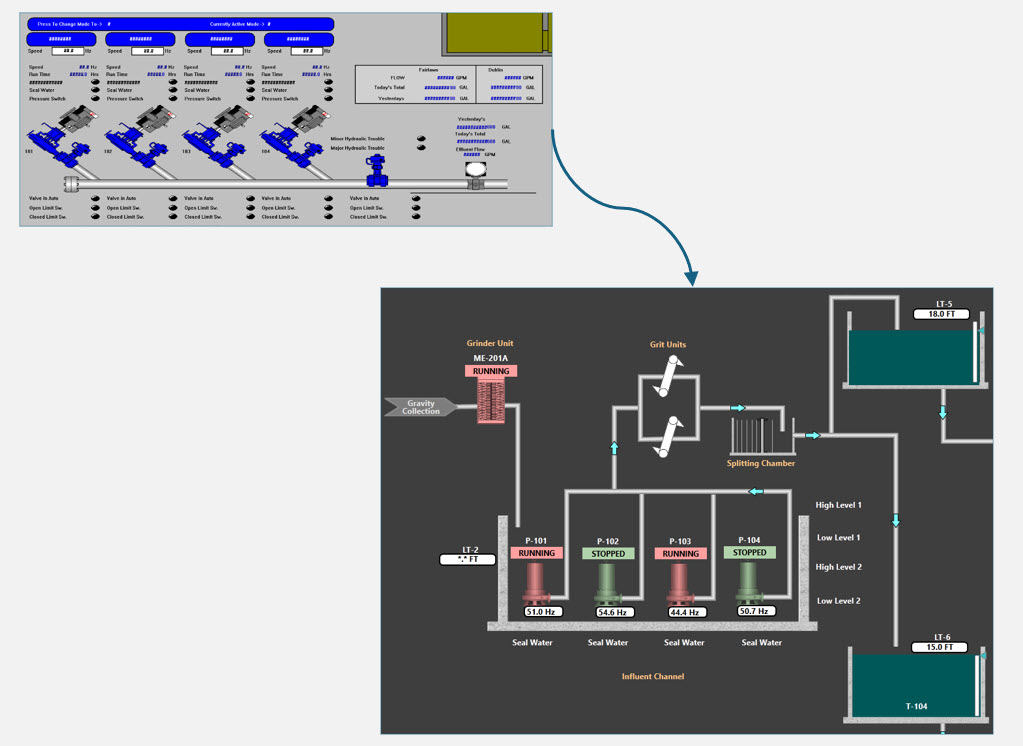
Standardizing graphics, visual elements and tag structure: Standardization begins with developing cohesive graphic criteria. The objective is to make every screen follow the same visual language—create matching styles for each object type (such as motors, valves, alarms, analogs) with its own symbol, fixed colors and set layout. For instance, make alarm pop-ups appear the same way every time, make symbols identical and set a color palette that never changes, thus improving operator responsiveness.
Software tag structure is crucial and is to be treated as a core architectural element. A hierarchical, clear and consistent tag-naming convention improves clarity, reduces maintenance time and supports integration with new devices or PLCs.
Designing for scalability and long-term flexibility: Scalability is essential, particularly for facilities that plan to expand and include treatment capacity or advanced equipment. An HMI system that is built around modular blocks and standardized components will easily support expansion needs. When a new device, controller, or process is integrated, changes are smooth and require less rework and fewer interruptions in process flow.
The vision phase establishes guiding design principles that influence every implementation decision. Symbols must look and behave the same way everywhere and every time to maintain consistent user experience. Initially, only broad views are addressed (specifics will be refined later). Clean screens and predictable layouts guide operators more efficiently. When each screen builds on a previous version, it elevates confusion. Adapting to a new screen then happens quickly and naturally.
3. Standardization: The strategy
Once the goal is clear, standardization becomes the execution strategy. This phase establishes guidelines for key HMI elements to thereby ensure consistency, efficiency and operator usability throughout the system.
Graphic standardization: Standard templates are built for common elements. To quickly ascertain equipment status, it is best to establish a set color palette and to decide on the uniform shape and animation of each element.
Dynamic faceplates are typically implemented at the HMI layer for each asset. Existing PLC data are used to present real time process values, control functions and diagnostic information within a single view, thus improving usability and troubleshooting efficiency.
Beyond operator usability, standardized graphics significantly improve engineering efficiency. After validated templates and faceplates are established, new equipment can be integrated with minimal design effort. Template updates can propagate across all instances—simplifying change management and reducing technical debt over time (Figure 3).

Tag naming and structure: To eliminate inconsistencies, ascertain how tags are currently organized, named and used across the HMI system. Rather than prescribing a single universal tag structure, this step should identify common patterns, constraints and owner-specific requirements that influence tagging. These findings are used to define a consistent tagging strategy and mapping approach that supports standardized HMI graphics and faceplates while also respecting owner-required conventions and downstream system dependencies (Figure 4).
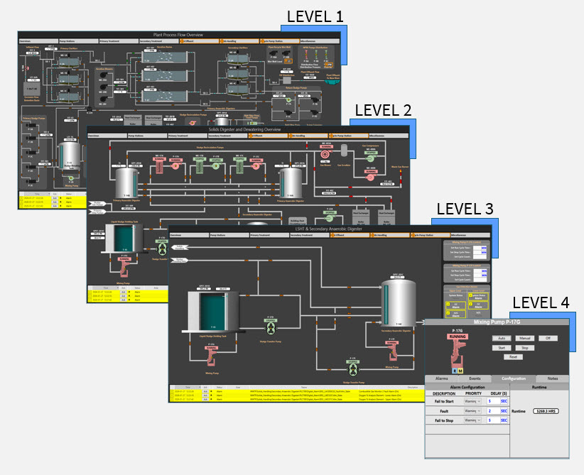
Multi-level hierarchical structure for navigation: A multi-level hierarchical screen structure improves navigation and reduces information overload by allowing operators to efficiently move from high-level site context to equipment detail.
- Level 1: Site overview displaying all major systems
- Level 2: Process area overviews focused on specific plant sections
- Level 3: Equipment-level graphics with detailed device information
- Level 4: Faceplates providing interactive real-time visualization and control
This approach ensures that operators access the appropriate level of detail for the task at hand without being overwhelmed by unnecessary information (Figure 5).
4. Integration and implementation: Bringing vision to life
With clear standards set, work shifts toward constructing the new HMI configuration, keeping tight alignment with existing PLCs and legacy equipment.
Integration with PLCs and existing equipment: Implementation begins with auditing PLC configurations, reviewing control logic and communication protocols and establishing a clear network mapping framework between PLCs and SCADA. Aligning the new tag convention with existing PLC structures ensures reliable and consistent communication.
Testing the system: Testing is a critical step for validating the performance of HMI under real operating conditions. Verification typically begins in a controlled or simulated environment to confirm correct tag mapping, screen behavior, navigation flow and faceplate functionality without impacting live operations. Testing is followed by field validation, wherein live process data are used to confirm accurate visualization, alarm behavior and response timing. Both manual and automatic control functions are exercised to ensure operators can safely monitor, intervene and control equipment as designed. This layered testing approach allows teams to confirm functional correctness, build operator confidence and validate the new HMI while minimizing operational risk.
Training and transitioning: Operator training is essential for successful adaptation. Training sessions should focus on updated navigation structures, standardized graphics and tag conventions and alarm management features. Running old and new HMI together will initially lower the chance for errors.
From a risk management perspective, a phased rollout with parallel operation of the legacy HMI and new HMI is a recommended best practice rather than a mandatory requirement. While some may choose to fully decommission the existing system and to commission the new HMI in a single system switchover, running both systems concurrently allows the modernized HMI to be validated against known and trusted behavior. Running systems concurrently enable engineers to compare system behavior, confirm tag mapping, alarm response, control logic and validate manual and automatic functions while the existing HMI system remains available as a reference.
This approach fulfills several objectives: enables field verification under real operating conditions, supports operator confidence and reduces the likelihood that configuration or logic issues propagate into live operations.
5. Results and impact: A system transformed
Following implementation, improvements are commonly observed across operational efficiency, diagnostics, scalability and safety.
Increased operational efficiency: Standardized graphics allow for faster equipment status recognition and quicker fault identification. The unified design and hierarchical navigation reduce time spent searching for information, while faceplates present detailed context without requiring extensive screen switching.
Enhanced data visibility and diagnostics: Improved access to real-time values and alarm logs support faster troubleshooting and more informed decision-making. Alarm management with consistent visual indicators improves awareness of critical conditions and supports timely response.
Scalability and futureproofing: Standardized tag conventions and templates reduce configuration effort when integrating new equipment and PLCs, preserving consistency as the system evolves. The architecture supports growth with minimal operational disruption, even as plant size and complexity increase.
Operator satisfaction and safety: Clearer visuals, consistent alarms and improved navigation reduce cognitive load and support faster responses to abnormal conditions and, additionally, contribute to safer operations and reduced likelihood of operator error.
Beyond immediate operational gains, the harmonized HMI establishes a shared reference model across operations, maintenance and engineering. Training materials become easier to develop, onboarding times are reduced and future projects benefit from a consistent design baseline.
A blueprint for future HMI upgrades
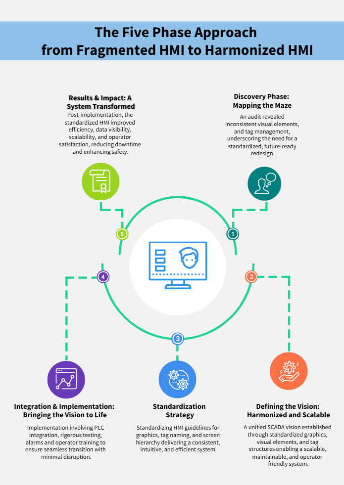
Transforming a fragmented and inconsistent HMI into a standardized cohesive platform is achievable through deliberate discovery, precise standards and disciplined implementation. Results include improved usability, stronger maintainability, enhanced diagnostic capability and a scalable foundation for future expansion (Figure 6).
HMI environments benefit from a harmonized approach and a practical blueprint for developing intuitive, resilient and safety-focused systems that support current operations and long-term organizational objectives.
Supreetha Sundararajan is an automation engineer, Karthicraja Vellaichamy Munisamy is an automation engineer and Vinoth Upendra Janardhanan is a senior automation engineer, all with CDM Smith Inc. Edited by Mark T. Hoske, editor-in-chief, Control Engineering, WTWH Media, [email protected].
Keywords
Human-machine interface, HMI screen design
Consider this
What safety and efficiency gains will operators bring with smarter HMI screen designs?
You also might like