Maximize fail-safe behavior so that for any single fault, the system is transitioned to a safe state. When creating the system’s communication and structure, reaction time in safe events can be the difference between a safe stop and machine failure.

Safety integrated functions in servo drives insights
- This article covers basic and advanced options for safety integration functions used in servo drives and controls, containing technical depth and relevant information, including motion control safety concepts and some history.
- Safe torque off (STO), safe stop functions and monitoring functions can help improve motion control safety.
- Motion safety functions can use industrial safety networks.
Safety integrated functions in servo drives and controls have basic and advanced options. Understanding technologies and related advancements can improve motion control implementations and reduce risk.
Motion control safety concepts, history
Before the 1990s, most safety precautions were handled by external hardware such as contactors, relays and switches. Emergency stops were used to physically remove power from drives and controllers.
In 1998, the IEC 61508 standard for Functional Safety was released for electrical systems. This provided standardization for safety concepts and laid out the groundwork for more technological advancements in safety.
After some time, servo drive manufacturers began implementing these changes, which led to the development of additional functions, including core functions (STO) in the 2000s and safe stop and speed functions (SS1, SS2, SOS, SLS, SLP, SDI) in the 2010s.
Also at this time, networked safety solutions and programming were being developed and implemented. Fieldbus solutions like Functional Safety over EtherCAT (FsOE), Profisafe, and CIP Safety were created to allow these safety functions to be easily programmed.
The progress of this technology and the standards that drive it have made machines safer to operate, easier to prevent accidents and easier to maintain.

Core functions of safe torque off (STO)
Before talking about safety functions, there are a few key acronyms to cover.
HWBB: Hard-wired base block (HWBB) is a state of the servo drive that is designed to shut off the servo drive current and servomotor movement. Different safety functions use this differently and depend on how the safety parameters are configured.
SRIS: The safety request input signal (SRIS) is the signal that determines when a safety function becomes active or inactive. This signal can be represented in multiple ways, such as a digital signal from a sensor or over a fieldbus such as FsOE, where it can be programmed to activate for whatever relevant application. When and how it activates depends on how the hardware is set up and the servo drive parameters.
STO: The most basic of safety functions is safe torque off (STO). This is the simplest function because, in essence, it is two states: On or Off. When STO is configured, when the SRIS signal is active, the servo drive goes into an HWBB state, thus not allowing any movement to the servomotor. STO is also the common error state when configuring safety functions. Figure 1 shows a general velocity and time plot of how this function safely stops motion.
A good example of an application where STO would be used would be for a door or guard with a sensor that shuts off the active drive when it is opened. The sensor on the door would set the SRIS signal to the drive and set the drive to go into HWBB state, disallowing motion. Although simple, STO can be used in multiple ways like this and is easy to set up, thus making it useful.

Safe stop functions
Safe stop functions are another type of safety function whose purpose is to bring unsafe motion to a safe condition in a safe way. The main difference between STO and safe stop functions is that STO will immediately disable torque-producing power, while a safe stop function will have some sort of active controlled stop. All safe stop functions are executed when the SRIS signal becomes active.
Many different types of safe stop functions can include safe stop 1 ramp monitored, safe stop 1 time controlled, safe stop 2 ramp monitored, safe stop 1 ramp monitored and safe operating stop.
When the safe operating stop (SOS) function is activated, the drive is put into position monitoring mode. This is often done after the servomotor’s torque is safely stopped, but the drive still has power available. In SOS, the position is monitored and will shut down if the configured position limits are violated. That is the main difference between safe stop 1 (SS1) and safe stop 2 (SS2). After SS1 stops the motor, the drive goes into STO state, and after SS2 stops the motor, the drive goes into SOS state. Figure 2 shows what the position monitoring looks like as a plot.
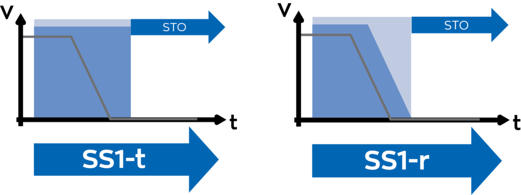
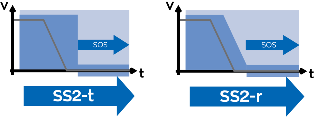
The other types of functions are time-controlled and ramp monitored. Time-controlled means that the servomotor will have a set configured amount of time to stop in either STO or SOS, depending on if it is in SS1 or SS2. Ramp monitored means that the servomotor’s deceleration is monitored in a set configured amount of time to stop in either STO or SOS, depending on if it is in SS1 or SS2. If the servomotor doesn’t decelerate as expected, a violation will occur, and the drive will be set to HWBB, and the power will be cut, no matter if it is in SS1 and SS2. This is shown in Figures 3 and 4.
There are many ways to configure and implement safe stop functions, and what should be used depends heavily on the application. SS1 works better for applications where a safety event occurs, and the servomotor comes to a stop but doesn’t need to hold torque. SS2 works better when a stopped servomotor does need to hold a torque. For example, SS1 would work better for a conveyor or rolling application where, if something goes wrong, the belts don’t get stuck in a locked position, potentially causing more damage or harm. SS2 would work better for a vertical axis or lift application where the stopped holding torque will keep a load from falling due to gravity.
Monitoring functions check motion metric safety
Monitoring functions are used to continually check that motion metrics are within safe limits. The Monitoring functions differ from the safe stop functions in that when the SRIS signal becomes active, monitoring functions will allow the servo motor to move at normal operations within safe limits. When the limits are exceeded, the servo drive will go into either STO or a safe stop function.
Monitoring functions can include safely-limited speed (SLS), safely-limited acceleration (SLA), safe speed range (SSR) and safe speed monitor (SSM).

SLS monitors the servo motor’s actual speed and will bring the servo motor to a safe stop if the speed limit is exceeded. When SRIS is active, speed will start to be monitored. The speed and timing limits are user selected, where s1 is the speed limit once SRIS becomes active, until t1 elapses. Then the speed limit is changed to s2, where the speed limit decreases linearly from once SRIS becomes active, until t2 elapses. The plot of this is shown in Figure 5. A good application for this function would be a packaging machine, where if one motor starts going too fast, the entire system can shut down quickly, reducing the risk of the machine tearing itself apart.

Safely-limited acceleration (SLA) function monitors the servo motor’s acceleration and will bring the motor to a safe stop if that acceleration limit is exceeded. Same as SLS, the acceleration and timing limits are user-selected. Once the SRIS signal becomes active, t1 is the time until acceleration starts to be monitored. Once t1 elapses, the acceleration is monitored and will bring the motor to a safe stop when the servo motor reaches the acceleration limit a1 in any direction. The plot of this is shown in Figure 6. A good application for this function could be a tension-controlled system, where any unwanted acceleration in one motor can be amplified into the other system, creating unwanted motion.
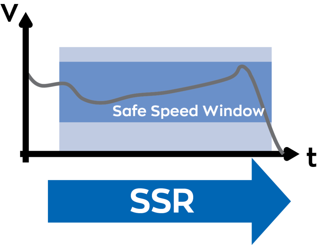
The SSR function monitors the servo motor’s speed and will bring the motor to a safe stop if the speed falls out of a user selected range. The main difference between SSR and SLS is the timing for when the speed starts to monitor, and SSR has a minimum and maximum speed where a limit violation can occur where SLS only throws a limit violation for a maximum speed. The plot of this is shown in Figure 7. A good application for this function could be a high-speed spindle motor, where deviations in spinning the motor too fast and too slow could cause problems with the tooling.
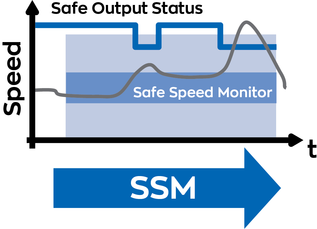
Safe speed motor (SSM) function monitors the servo motor’s speed and will control an output signal (SSMOS) based on whether or not a limit violation has occurred. The speed and timing limits are again user-selected, where speed monitoring will start once t1 elapses. Once the speed limit s1 is reached, the SSMOS signal will be on and only turned off once the motor reaches a lower speed limit s2. The plot of this is shown in Figure 8. Good applications for this function could include controlling machine guards by using SSMOS as a digital signal based on motor speed and/or using SSMOS as a software signal to trigger a routine to bring the motor to a desired speed.
Networking access to motion safety functions
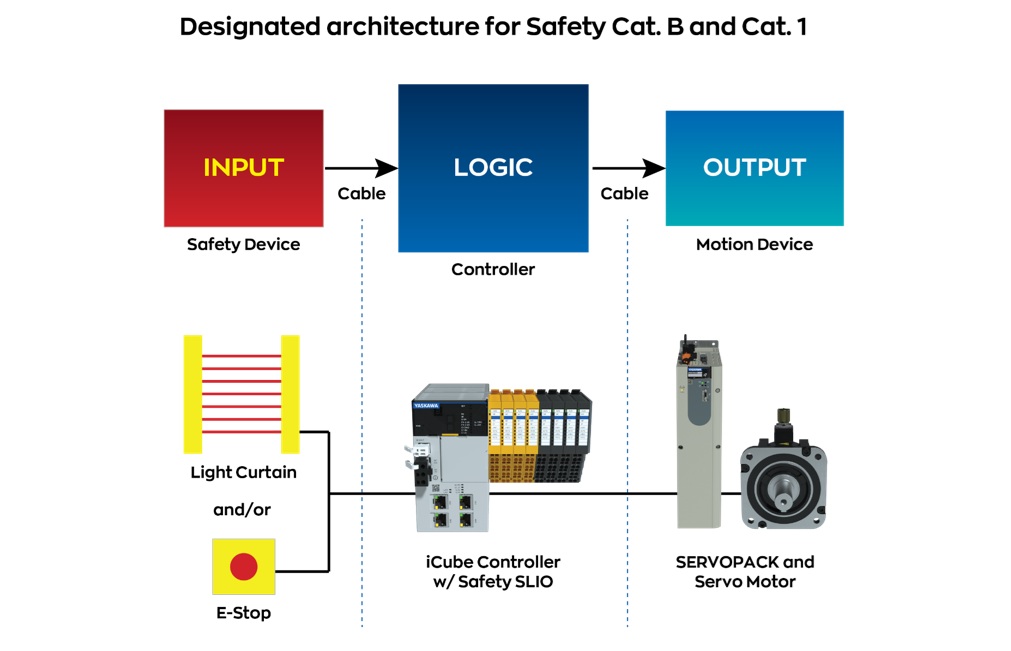
With these functions, safety applications already seem endless. There is more to correctly setting up a system that includes these safety mechanisms. Many of the signals that were referenced with these safety functions can be directly accessed either over a network in software or digitally to control sensors, actuators, machine guards, etc. Figure 9 shows a simple way of setting this up.
When setting up these signals digitally, there are a few key safety features to consider. ASM-X and other devices can use redundant signals. This means there are two digital inputs/outputs for one signal. This is used so the safety device can detect if the signal is unreliable. If both inputs/outputs don’t agree, the machine can go into a safe state. The signals have test pulses to again check that these signals are not hung up.
These digital signals are often connected to other safety I/O modules, safety relays or safety programmable logic controllers (PLCs). This is to ensure these important signals are correctly sent to and from device to device, with all devices in a system being able to detect when something is wrong and can put the machine in a safe position if that occurs.
When setting up these signals over a fieldbus, there are many things to be aware of. The data from devices are sent over a safety version of whichever device communication your system uses (FsOE, Profisafe, CIP Safety, etc.) and will use a safety PLC to reliably communicate the information. The safety PLC will send information with cyclic redundancy checks that include checksums to detect that the data sent was the same as what was received. When programming over a safety fieldbus, there are more checks and balances to ensure that what is programmed is valid and safe. Thus, programming safety devices often takes more time, effort and data checking. This is supplemented with each safety device having its own individual safety ID to confirm that data is going to and from the correct devices. These devices have watchdog time monitoring, where if a device in the system fails, it can put the machine in a safe position.
Summary advice on motion control safety
For whatever application is being used, however it is implemented, these are the important goals to keep in mind. Maximize fail-safe behavior so that for any single fault, the system is transitioned to a safe state. When creating the system’s communication and structure, reaction time in safe events can be the difference between a safe stop and machine failure. The time between the detection of a hazardous condition and a safety response must be known and as small as possible. Selecting and configuring the correct safety devices helps with this process. Most importantly, all hardware, firmware, and software must be verified, validated, and documented heavily to ensure all elements of the system are set up correctly. When setting up systems like this, it’s important to have contact with the right experts when support is needed.
Roman Skorupa is product support engineer, Yaskawa America Inc. Edited by Mark T. Hoske, editor-in-chief, Control Engineering, WTWH Media, [email protected].
Keywords
Motion control safety, machine safety, safety integrated functions
Consider this
Are you using modern technologies to lower motion control risk and improve machine safety?
You also might like
Read another Control Engineering article from Roman Skorupa, Advantages of multi-axis servo drives in the world of automation.