Why servo motor sizing matters: This tutorial article covers the servo motor sizing basics, key considerations and common pitfalls of properly sizing a servo system to an automation application.
Servo system sizing insights
- Learn how properly servo system sizing requires balancing the requirements of the application with the capabilities of the motor, drive and mechanical system.
- Understand what needs to move, how it needs to move, and what mechanical and electrical factors can affect that motion, so engineers can select a system that meets the required performance without unnecessary cost or capacity.
- Evaluate these application factors during the design process to help prevent unexpected faults, reduce machine downtime and improve the overall reliability and lifetime of the servo motor system.
When servo motor panels and applications are built, they are not designed just to simply work. They are designed to be reliable, and last as long as possible. The best way to ensure this is to properly size all devices being used in a system. Proper sizing affects not only thermal performance and machine life, but also improves positional accuracy, efficiency, and stability. Under sizing of an application leads to poor motor response, overheating, and overload faults. While oversizing can increase device cost and motor inertia and may reduce efficiency at some operating points. It all comes down to being balanced. This will optimize performance, efficiency, and machine life.
When an application is being designed, this usually is the first thing that must be reviewed. This is how crucial it is that the system is properly sized. It is imperative that all possible scenarios and aspects are reviewed in this process, so a device won’t have to get changed out in the middle of the design portion. We will review the fundamentals in sizing each aspect of an application.
Application specific motion control
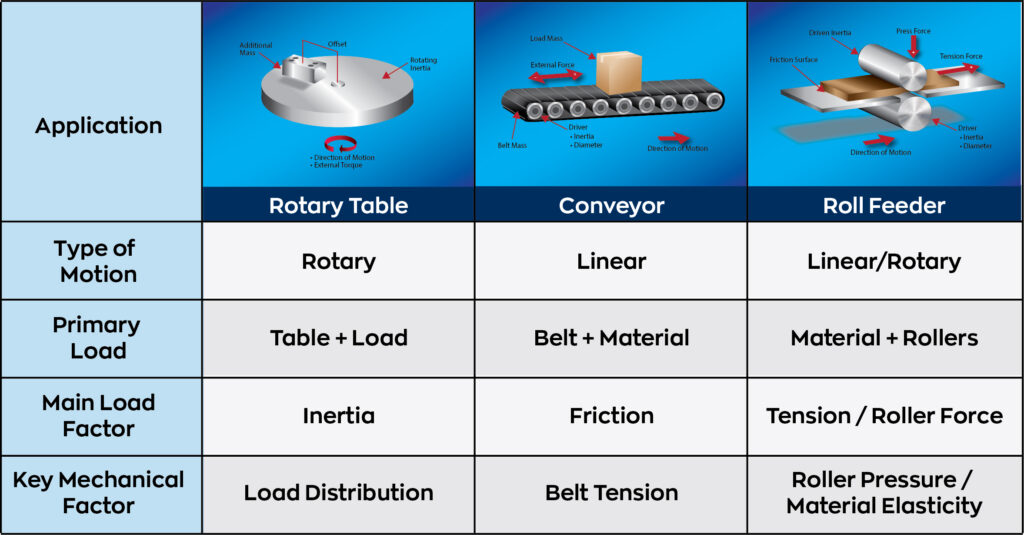
The first question you have to ask yourself is simple, “What needs to move?” Understanding the load that needs to be moved is the main basis of correctly sizing an application. To do this you must consider the total mass and inertia of the load that is moved, whether that movement is rotary or linear; horizontal or vertical, whether the load is constant or can change throughout its movement, and external forces such as gravity, friction, or tension. A machine’s load is the main thing that drives sizing. Some considerations may suggest use of smaller motors and drives. At the end of the day, the size of the load is what sets the bounds of what is possible. It is why it is a good strategy to start here to get a range of physically possible combinations. The load ultimately establishes the fundamental limits of what the servo system must be capable of moving. You can see how different applications have varying factors in Figure 1.
The next question is “How must this load move?” Defined metrics for motion include speed, acceleration, deceleration, frequency or movement, motion profile, positioning precision, and holding requirements. These are the more application specific things that can help narrow down from a range of sizes to just one or two sizes. The analysis of correctly selecting these metrics is critical. Any incorrect sizing based off a motion-based application decision can lead to poor performance or even system destruction. With knowing what needs to move and these motion metrics you can determine the following. Acceleration and Deceleration determine peak torque. Frequency of cycles determines thermal effects. Motion profile and variety of motion determine the combination of torque, speed, and power requirements of the system. Position precision determines needs for dynamic response and encoder selection. Holding requirements determine continuous torque requirements.
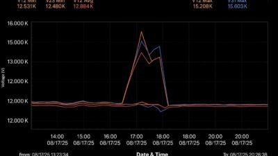
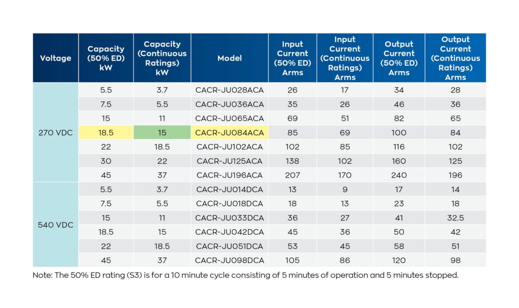
There are other factors that can come into play that can help shrink a system. Some drives have a duty cycle rating, that allows higher ratings to be utilized for shorter periods of time. For example, some spindle drives have a 10 minute (5 minute on, 5 minute off) 50% ED or “duty dycle” rating. For example, a 240VDC spindle drive that usually runs at 15kW continuously can reach up to 18.5kW when controlled at the duty cycle shown (Figure 2).
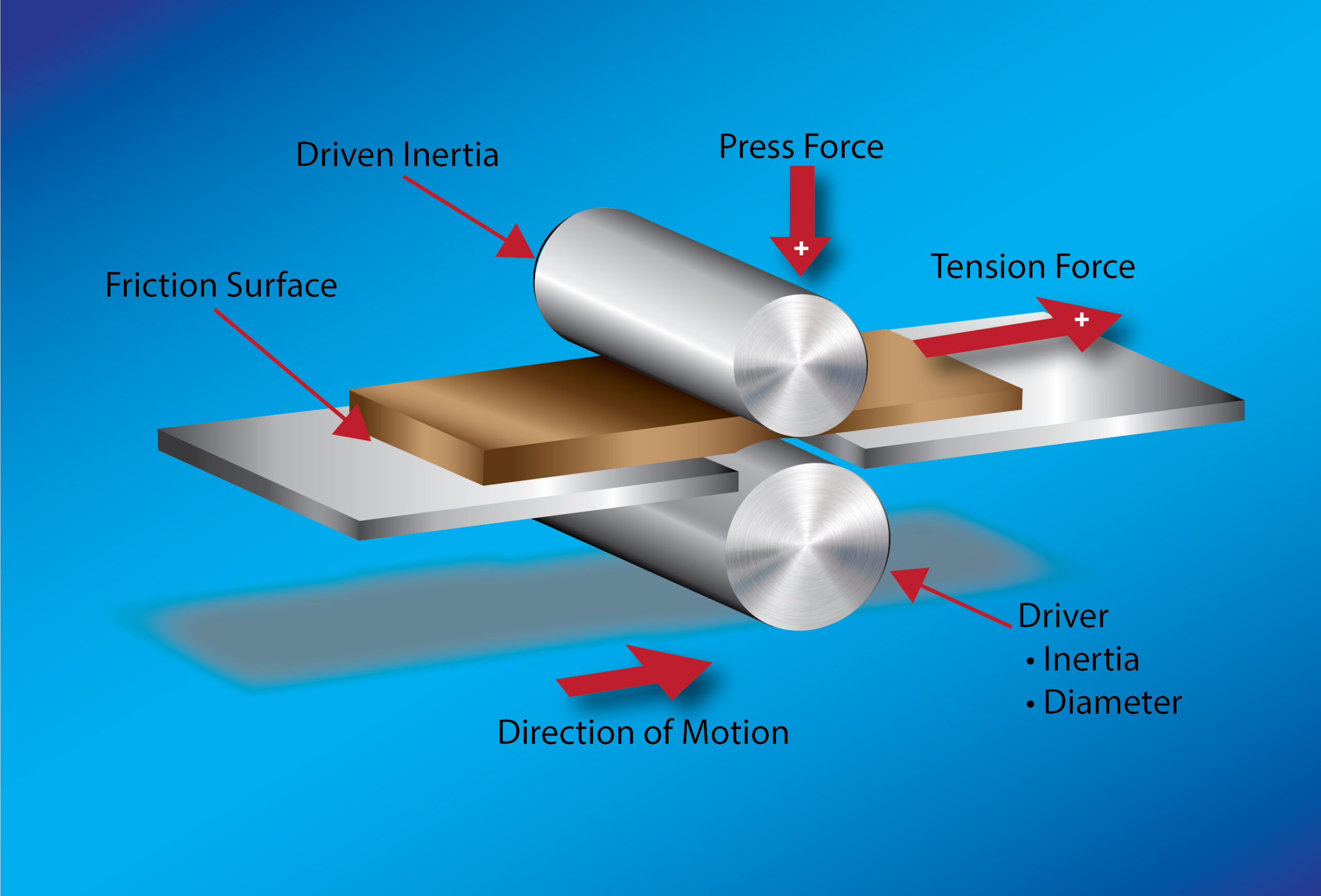
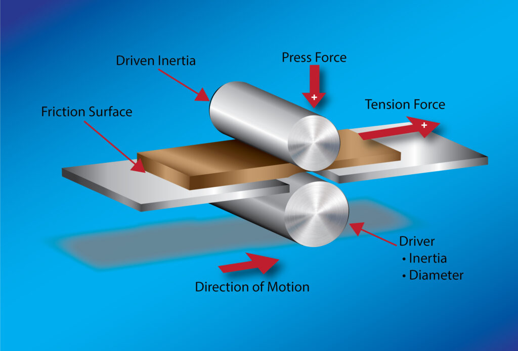
Another example can be found in multi-axis systems where mechanical constraints cause one axis to motor while another regenerates. In a roll-feeder system (Figure 3) with independently controlled drive rollers, one servo may supply torque to move the material while the other is driven by the material and returns energy back to the DC bus. In systems with a shared DC bus, this regenerated energy can be used by the motoring axis rather than being dissipated entirely through a braking resistor. Understanding the expected direction and magnitude of power flow between axes can therefore help optimize the overall drive and power system. When using a common DC bus, the total bus capacitance must also remain within the manufacturer’s specified limits. Exceeding the allowable capacitance can place excessive demands on the system’s pre-charge circuit, potentially causing charging faults, improper startup, or damage to drive components.
Selecting the motor
The next consideration is how the load is connected to the motor. There are many ways to do this, each coming with their own advantages and disadvantages. “Backlash” is a key term in this discussion. Backlash is mechanical lost motion caused by clearance between mating components in a transmission. When the direction of motion changes, this clearance must be taken up before the driven load responds.
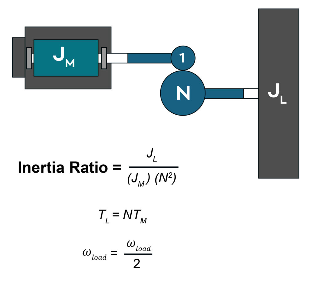
Another term to know is “inertia.” Inertia is the measure of a load’s resistance to changes in its speed. The motor and load both have inertia, and the common metric used for sizing is their ratio where
J=Jload /Jmotor.
For applications where high performance is required, 5:1 is the generally a good figure to use as a maximum. As inertia ratio goes down to 2:1 or 1:1, the performance can increase. Where high performance is not as critical, ratios of 10:1 or even 100:1 is not uncommon. Gearboxes and pulley systems can help change that ratio seen by the motor by the gear ratio, where
Jreflected=Jload/N2
where N is the gear ratio. This idea is shown in Figure 4.
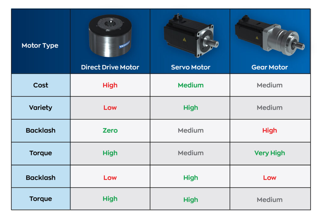
The cleanest, smoothest load to motor connection is direct drive. A direct drive motor is a motor where the load is directly connected to the rotor. This option allows absolutely zero backlash since there is no transmission mechanism between the power conversion to the load. Direct drive setups also have a longer operational lifespan due to the removal of wear prone components. They often come with low speed, high torque ratings since the high motor pole count can lead to excessive electrical motor frequency. The disadvantages to direct drive motors is that they are often bulkier due to needing these large electromagnetic components, they often run hotter since the motor sits directly next to the load without a buffer, and they are often much more expensive due to these reasons and the high cost of this type of technology. These are best used in high precision, high torque, and low speed applications. These include rotary tables, large robotic joints, large pick and place machines and wind turbines.
The next level of this is a regular servo motor. A servo motor has a small amount of backlash within the motor and includes extra variable backlash depending on the transmission mechanism used. However, they are a lot cheaper than direct drive motors and come with a much larger variety in torque and speed ratings. Then a custom gearbox, pulley, rack and pinion, etc., can be used to help dial in the torque ratings required for a servo system, with the advantage being that custom gear ratios can be used. These do introduce more backlash to the system, with pulleys introducing near zero backlash, gearboxes introducing moderate backlash, and rack and pinion introducing high backlash.
Another motor option is a gear motor. This combines the gearing system, that could be used externally from a servo motor, internally, so they are packaged together. Although this limits the application to specific gear ratios, there are advantages to these being packaged together. Compared to a servomotor coupled to a gearbox, these gearmotors are smaller in size, have optimized alignment and efficiency out of the box, and have simpler feedback and closed loop control to more precisely control position.
Taking these decisions into account allows the user to find the most suitable sizing options for an application. The different options and their advantages and disadvantages are shown in Figure 5.
Questions to ask when sizing a servo motor system
With all of that in mind, the steps of sizing a system could look like this. First, what needs to move? The important information is the load’s mass, and how that mass is distributed. For a rotary load, these characteristics determine the load inertia, which represents the load’s resistance to changes in rotational speed. This can be calculated depending on the geometry and orientation of the load. Figure 6 shows the differences in calculations based on that geometry and orientation.
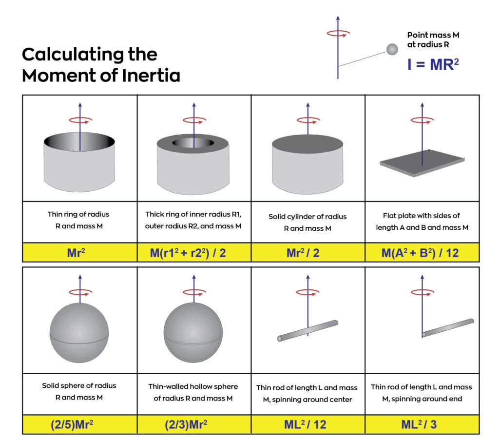
Next, how must the load move? The motion profile defines the required speed, acceleration, deceleration, and frequency of movement. Maximum speed establishes the motor’s speed requirement, while acceleration and the total inertia determine the torque required to accelerate the load using T = Jα, where T is the internal torque, J is the calculated total load inertia, and α is the angular acceleration. Additional torque from friction, gravity, and the machine’s process must then be considered to determine the motor’s peak torque requirement. These requirements can then be compared with a motor’s torque-speed curve to determine whether the motor can provide the required peak and continuous torque at the required operating speeds.
Finally, “What other factors can help optimize the system?” This is where creativity can become part of the sizing process. If the application allows a lower load speed, a gearbox can trade motor speed for additional output torque. For a gear ratio of N, the following relationships occur.
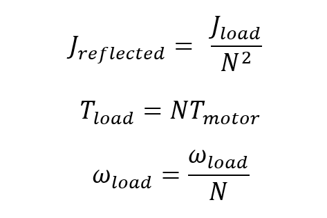
If the application has periods of high load followed by periods of low load, the motion profile and duty cycle may allow a smaller motor or drive to meet the application’s requirements without exceeding its thermal limits. In multi-axis applications, regenerative energy from one axis may also be used by another through a common DC bus. By considering the mechanical system, duty cycle, power flow, and operating requirements together, the engineer can often reduce system size and cost without sacrificing the required performance.
This is a basic way to a general idea of what a system should look like from a sizing perspective, but systems can get complicated quickly. Drive manufacturers often have sizing software that can tremendously help in sizing a system more easily. Free sizing software can simplify the process. This allows the user to skip complicated calculations by inserting the metrics of a system and outputting the best sizing options along with details about the motor and system.
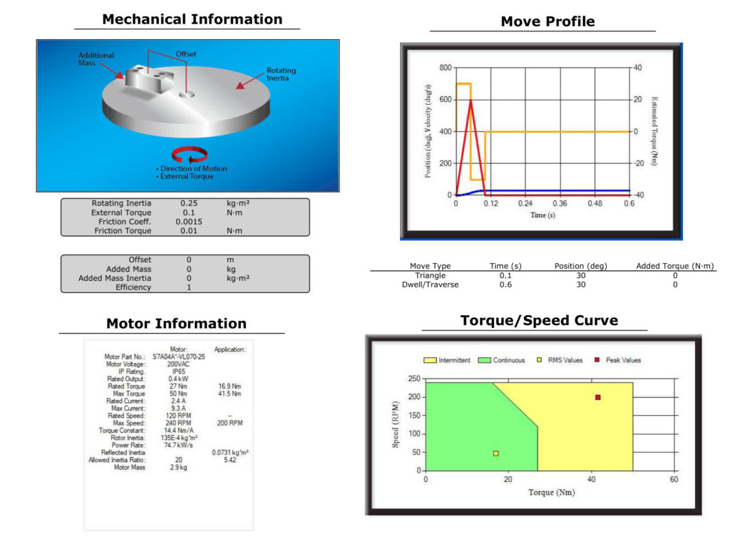
Sizing software allows the user to analyze many mechanisms and assists in calculating load inertia, mechanism metrics, and transmission computation easily. Once the mechanism is selected, the user can specify the motion profile. Then all motor information gets laid out. The software will confirm the motors’ values of the important key sizing metrics in max and rated torque, max and rated speed, inertia ratio, and even cost factor. Once a motor is selected, all motor details and regen info are given. Figure 7 shows what this process yields. Training modules and practical examples allow users to do this on their own. For even more complicated systems, a user can get support from a manufacturer’s technical representative.
Properly sizing a servo system is ultimately a process of balancing the requirements of the application with the capabilities of the motor, drive, and mechanical system. By understanding what needs to move, how it needs to move, and what mechanical and electrical factors can affect that motion, engineers can select a system that meets the required performance without unnecessary cost or capacity. Taking the time to evaluate these factors during the design process can help prevent unexpected faults, reduce machine downtime, and improve the overall reliability and lifetime of the system.
Roman Skorupa is product support engineer, Yaskawa America Inc. Edited by Mark T. Hoske, editor-in-chief, Control Engineering, Arrowfly, [email protected].
Keywords
Servo motor sizing, motor sizing tutorial
Consider this
Are you sizing your servo motors appropriately for your applications?
You also might like
For more from Skorupa, see:
https://www.controleng.com/advantages-of-multi-axis-servo-drives-in-the-world-of-automation