I have a noisy process. How does that affect my PID controller? Can I tune my controller like I always do, or do I have to change tuning because of the noise?
Insights about how noise affects PID controller performance
- Controller gain passes noise to the controller output, integral suppresses noise, and derivative amplifies noise.
- Tuning when noise is present usually requires lowering controller gain, speeding up integral, and eliminating derivative altogether. This reduces the controller’s ability to reject disturbances.
- Adding a noise filter can help reduce noise, which allows restoring more aggressive tuning.
In the real world, process noise is everywhere, and it cannot be ignored. Process noise adversely affects how a proportional-integral-derivative (PID) controller works. If it is very severe, we must take measures to minimize process noise, and unfortunately these measures also adversely affect PID controller performance.
In this and the next two installments we are going to cover how noise:
- Affects controller gain, integral and derivative response.
- Affects open, closed and heuristic controller tuning methods.
- Can be managed by signal filtering. We will also examine the impact filtering has on controller tuning and performance.
What is noise in industrial process plants?
The two types of noise we typically run into in process plants are:
- White noise: Noise that doesn’t have a pattern. Statistically white noise has low autocorrelation, which is a fancy way to say you cannot predict the next value from the current value or that it has no trend.
- Cyclic noise: Noise that contains one or a collection of waves, typically a sine wave. These can be caused by vibrating pipes, motors, cycling equipment, etc. If cyclical noise is your main problem a moving average filter may be a better solution than the typical first order (low pass) filter.
The one common property of noise in a process control context is it is fast relative to the actual process response. We would like our PID controller to ignore it, but unfortunately if it is measured the controller is going to respond whether it needs to or not. Understanding how a PID controller responds to process noise will help us develop the best approach to managing noise. This can include filtering and tuning tweaks as well as the judicious use of advanced PID features.
How does noise affect controller gain?
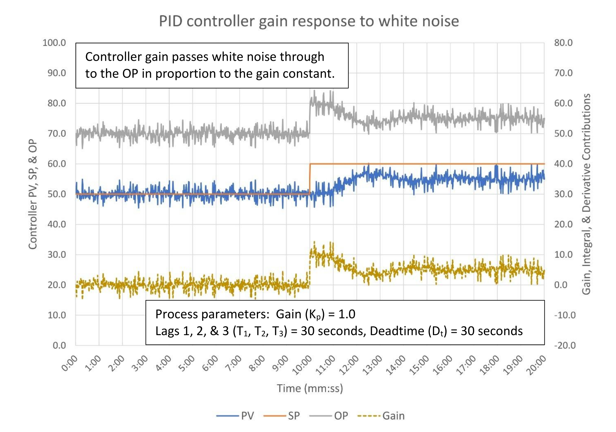
In Figure 1 we see how white noise is passed through to the controller output (OP) by the controller gain (K – gold line). The amplitude of OP swings depends on the controller gain; higher gain results in larger swings. If the process is slow like this one the excess valve movement doesn’t materially affect the process. It does, however, accelerate valve wear. If the process were faster the excessive valve movement could set up a positive feedback cycle that would increase the apparent noise and potentially affect controller stability.

Figure 2 explores what can happen when a fast process has (in this case) cyclic noise that is near the loop’s resonant frequency. Shortly after the +/- 5% cycle starts at the 1 minute mark the feedback quickly increases the swing to approximately +/- 9%. Depending on the approach to resonant frequency the swings could become very pronounced. You will need to pay careful attention to managing noise when this happens.

With respect to controller tuning if there is unmitigated noise controller gain will often be lowered to reduce the impact of process noise on the process. This may negatively impact controller performance.
How does noise affect controller integral?
Integral because of its nature is largely immune to fast process noise. In Figure 3 if you were to only look at the controller output (OP) you would be hard pressed to say that there was any process noise at all.

Figure 4 shows us that even when a fast process has comparably fast integral tuning, even cyclic noise is only slightly reflected in the controller output.

As noted in the controller gain section, unmitigated noise may lead to reducing controller gain to manage stability. Integral’s immunity to noise allows us to speed up integral to help make up for reduced controller gain – with the tradeoff that integral is slower to respond to disturbances and can produce overshoot and controller oscillations.
How does noise affect controller derivative?
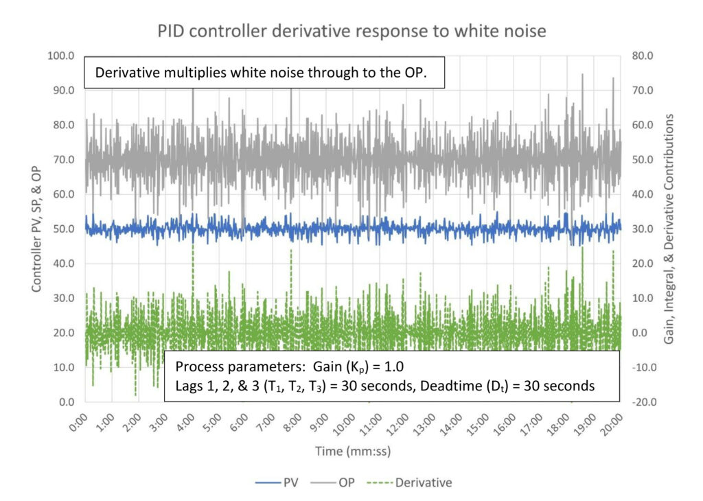
Figure 5 illustrates why derivative is rarely used, and why conventional wisdom often counsels against its use. Derivative greatly amplifies process noise. In this case a quite modest derivative tuning constant of 0.05 minutes converts a +/- 5% white noise signal into a controller output response peaking at +/- 25%. Obviously in the real world no control valve can respond this fast, but it just might shake itself apart trying.
There’s no point in putting up a figure showing derivative response to cyclic noise. It’s just going to show more of the same; a relatively small noise band gets multiplied by a modest derivative constant.
In summary, process noise is passed through by gain, mostly has no effect on integral, and is multiplied by derivative. From a practical standpoint this means that a noisy process will be tuned with less gain, more integral, and will never have derivative. Since controller gain is our primary tool for disturbance suppression, and derivative can be deployed to help, reducing controller gain and eliminating derivative will permit disturbances to create bigger and longer-lasting process upsets.
How does noise impact controller tuning?
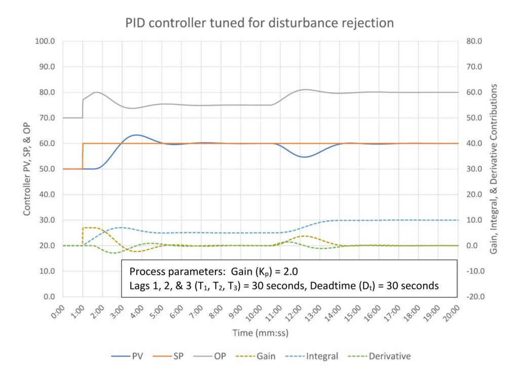
Figure 6 shows the same moderate self-limiting process we’ve been using since PID spotlight part 7 tuned for disturbance rejection. It has a 1.49:1 lag/deadtime ratio, which means that it is going to be somewhat difficult to tune and will have a limited stable and effective controller gain range. Having multiple lags, it will also benefit from having derivative. Disturbance rejection tuning intentionally pushes controller gain into oscillatory behavior. In short, this is a fragile controller; we should expect noise to be a problem.
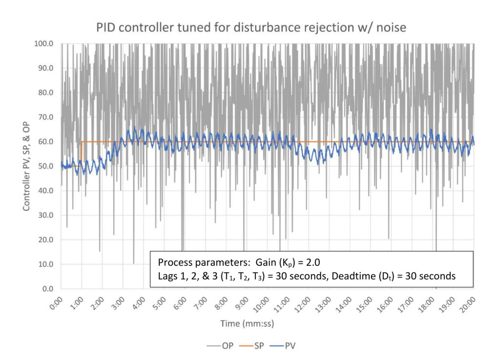
In Figure 7 we see that a moderate amount of white and cyclic noise causes the controller output (OP) to go crazy (technical term). However, note that in this case the tuning still works. The process variable (PV) still follows the setpoint (SP) and the disturbance is corrected reasonably quickly. Retuning this controller is only required to get the OP movement under control (read “save the valve” and to make the trend look better.)
Once we change to controller tuning to manage the noise, we will have a process response that looks a lot like Figure 8. The first thing we did when retuning the controller was to eliminate derivative. There is no derivative setting that doesn’t cause excessive controller output (OP) movement and still helps controller performance. The second thing we did was reduce controller gain until we get the white noise reasonably under control and the cyclic noise reduced to a tolerable level. We landed on a controller gain (K) of 0.25, which reduced the cyclic swing in the controller gain contribution (gold line) to one fourth the size of the cyclic noise. The third thing we did was speed up the integral to attempt to recover some of the controller performance we lost.

In the end the response to a disturbance has been slowed down (about 4.5 minutes to eliminate a disturbance versus 3.0 minutes), and the size of the disturbance has increased (about 8% max deviation from SP ignoring noise versus 5%). There appears to be more oscillation in the response, but this gets a little bit lost in the noise. The response to a setpoint change is slower, but speed of response to a setpoint change wasn’t a performance requirement. In total noise has adversely affected our ability to tune this controller to reject disturbances.
Quick start noise filter guide for better PID tuning
We will discuss filtering in detail later, but for most controllers a simple first order (low pass) filter will suffice. As a general rule a first order filter should be set as small as practical, but generally not larger than 10% of the integral constant:
Tfilter < 0.1 * Ti
We want to minimize the noise filter constant because to the controller it looks like just another process lag, and just like any other lag it will increase apparent deadtime. If this is big enough this will require retuning the controller and will affect the controller’s ability to manage disturbances.
How does adding a noise filter affect our process?
In Figure 9 we’ve set the noise filter to one-tenth the integral constant, or 0.14 minutes. This has reduced controller output movement from crazy to merely excessive. Looking at the tuning contribution trends we can see that derivative is the source for virtually all the excessive movement. Overall the process variable trend looks like a noisy version of the clean process response in Figure 1. The amount of time off setpoint from the disturbance is still about 3 minutes and the maximum deviation from setpoint is still about 5%. Unfortunately we cannot leave derivative like this, which means that we must reset the tuning to constants that do not require derivative.
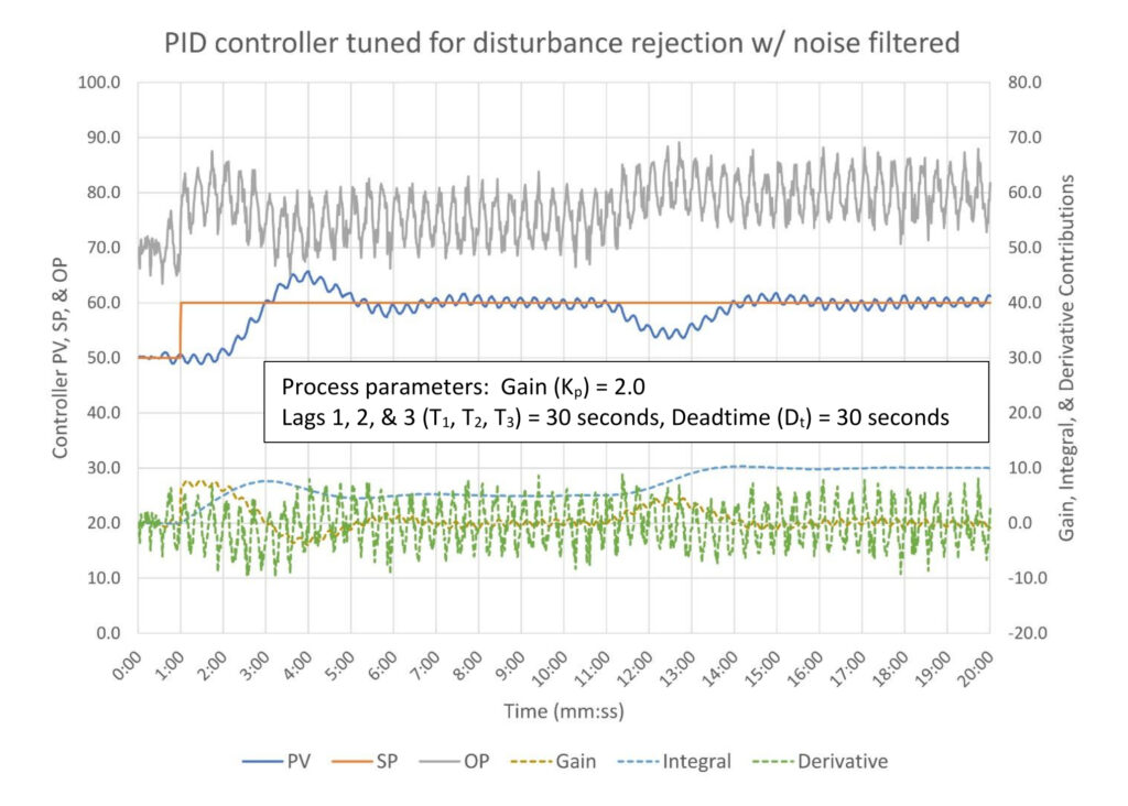
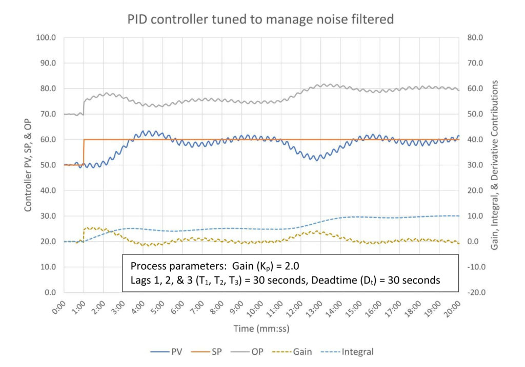
I used heuristics to set the tuning constants at the maximum gain and fastest integral possible without the use of derivative. Figure 10 shows the result. There is some oscillation passed through to the controller output by the controller gain, but it isn’t excessive. The controller eliminates the disturbance in about 3.5 minutes and limits the deviation from setpoint to about 8%. Controller performance is worse, as expected, but it is better than what we could achieve by retuning alone.
Summary of how to adjust tuning for a noisy process
Process noise causes excessive controller output movement and in the worst cases can cause excessive cycling of a process. Controller tuning can be modified to minimize the impact of noise by eliminating derivative, lowering controller gain and speeding up integral. This will slow down controller response, especially if the controller would benefit from the application of derivative.
A simple low pass filter can be used to minimize noise, but adding a filter is the equivalent of adding another lag to the process. This will increase apparent process deadtime, which may require slowing the controller down. Regardless, it may still allow more aggressive tuning by tamping down the process noise.
Ed Bullerdiek is a retired control engineer with 37 years of process control experience in petroleum refining and oil production. Send comments and questions to [email protected]. Edited by Mark T. Hoske, editor-in-chief, Control Engineering, WTWH Media, [email protected].
CONSIDER THIS
A PID controller responds to whatever it sees regardless of whether it is real or just noise. What must we do to ensure the controller responds to the signal and doesn’t respond to the noise?
PID series from Ed Bullerdiek, retired control engineer
Part 1: Three reasons to tune control loops: Safety, profit, energy efficiency
PID spotlight, part 2: Know these 13 terms, interactions
PID spotlight, part 3: How to select one of four process responses
PID spotlight, part 4: How to balance PID control for a self-limiting process
PID spotlight, part 5: What does good and bad controller tuning look like?
PID spotlight, part 6: Deadtime? How to boost controller performance anyway
PID spotlight, part 7: Open-loop tuning of a self-limiting process
PID spotlight, part 8: Closed-loop tuning for self-limiting processes
PID spotlight, part 9: Heuristic tuning for a self-limiting process (part A on heuristic tuning)
PID spotlight, part 10: Heuristic tuning in a self-limiting process
PID spotlight, part 11: How a PID controller works with an integrating process
PID spotlight, part 12: What does good and bad controller tuning look like?
PID spotlight, part 13: Deadtime: what’s the best that I can do?
PID spotlight, part 14: How open loop tuning works in an integrating process
PID spotlight, part 15: Open loop tuning of near integrating processes
PID spotlight, part 16: Closed loop tuning of an integrating process
PID spotlight, part 17: Heuristic tuning of an integrating process
PID spotlight, part 18: Identifying control valve performance problems
PID spotlight, part 19: PID controller tuning mechanics
PID spotlight, part 20: Tuning with bad valves
More on PID and advanced process control from Control Engineering.