When you change your level controller setpoint the response upsets your process. What is the best technique to shape the response to your needs?
Insights about shaping PID controller response
- An appropriately slow setpoint ramp can move an integrating process to a new value without an undue disturbance to the rest of the process. A setpoint filter can still allow a significant disturbance to the rest of the process after a setpoint change. However, properly set a setpoint filter will prevent the process variable from overshooting the new setpoint even when the controller is aggressively tuned. Set the setpoint filter equal to the integral constant as a starting point and adjust as necessary.
- The integral only on setpoint change algorithm, like a setpoint filter, can also allow a significant disturbance to the rest of the process after a setpoint change. Slowing down the integral constant will reduce the size of the upset as well as extending the time for the process variable to reach setpoint.
- As a general rule, level controllers should be set up to use the integral only on setpoint change algorithm except when tuning to follow setpoint changes. Other integrating processes that are tuned for aggressive response generally should not use integral only on setpoint change; this should be a conscious decision based on the needs of the process.
Integrating processes present us with the same proportional-integral-derivative (PID) controller tuning problem that lag dominant processes have; the controller output can take a very large jump after a setpoint change (see PID spotlight part 29). With the exception of very slow surge tuning, this a problem that is independent of how the integrating process is tuned. And while in refining we rarely change level controller setpoints, it does happen and, if handled poorly, can cause a very large disturbance to the process.
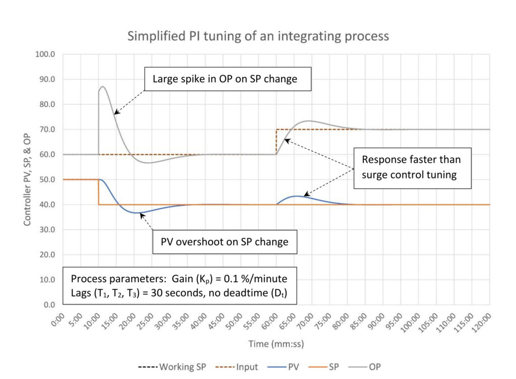
Figure 1 is an integrating process tuned using the simplified integrating process PI tuning calculation introduced in PID spotlight part 8 Table 1. The maximum deviation from setpoint is set at 20%; this is not very aggressive control. Nonetheless, with a controller gain of 2.5 a 10% change in setpoint (SP) will result in a 25%+ change in controller output (OP). If this were a feed drum, the process would experience a sudden change in feedrate of more than 40%. This would be followed by the process variable (PV) overshooting the SP before settling on SP; an unavoidable result of changing an integrating process’s setpoint. There are few processes that wouldn’t find this very disruptive. Can a setpoint ramp, setpoint filter or using the integral only on setpoint change algorithm alleviate this potential problem?
Setpoint ramp
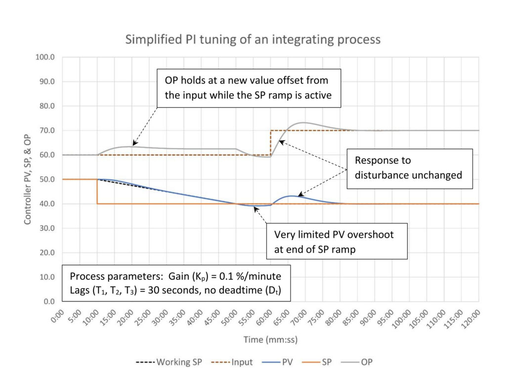
In Figure 2 a setpoint ramp has been set to move the setpoint down 10% over the course of 40 minutes. To get a change in level there must, of course, be a difference between the input and output flow from the drum. At the requested ramp rate the output flow slowly increases to slightly over 63% and slowly settles back to 62.5% until the ramp ends. This roughly 4% increase in feed rate for 40 minutes will cause a minor bump to the process. Obviously the slower the ramp rate the smaller the bump to the process, and conversely a faster ramp will result in a bigger bump. Finally, as expected, the controller response to a disturbance remains unchanged.
Setpoint filter
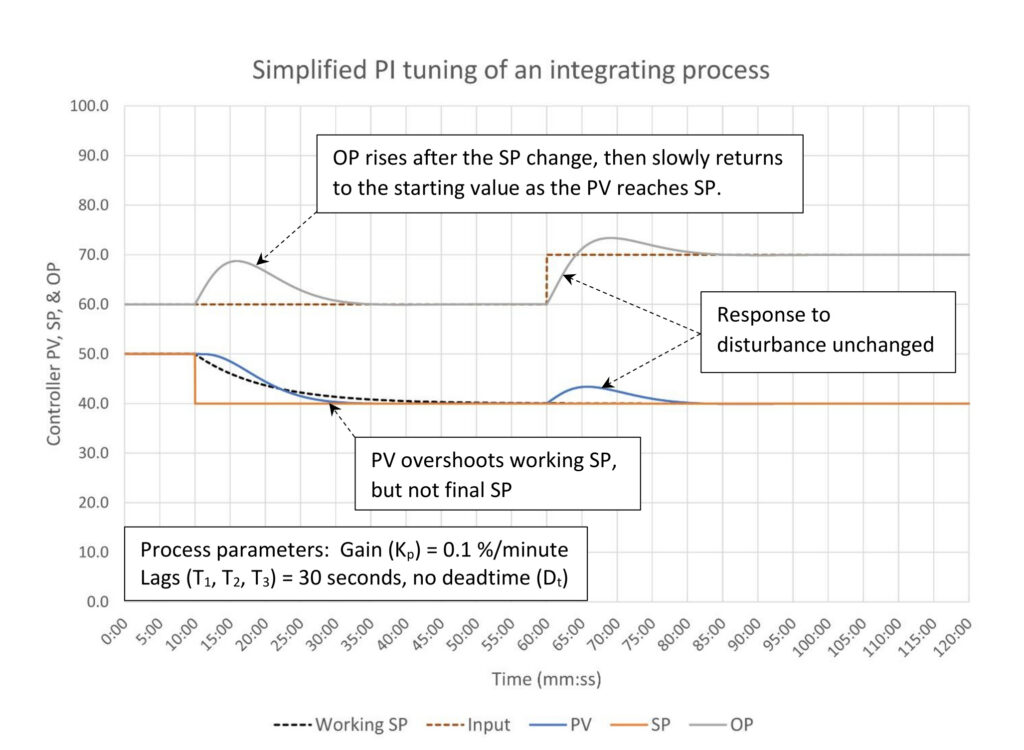
Applying a setpoint filter as seen in Figure 3 has a completely different impact on how the controller output (OP) responds to a setpoint change. A setpoint filter of 10 minutes was used with the goal of getting to the new setpoint in about 40 minutes, the same as the setpoint ramp used in Figure 2. The OP peaks at 68.73% shortly after the SP change, which is an almost 15% change in feedrate to our downstream process. If our goal is to not upset the downstream process, a setpoint ramp is clearly better. If, however, our goal was to prevent the PV from overshooting the SP then adding the SP filter worked very well.
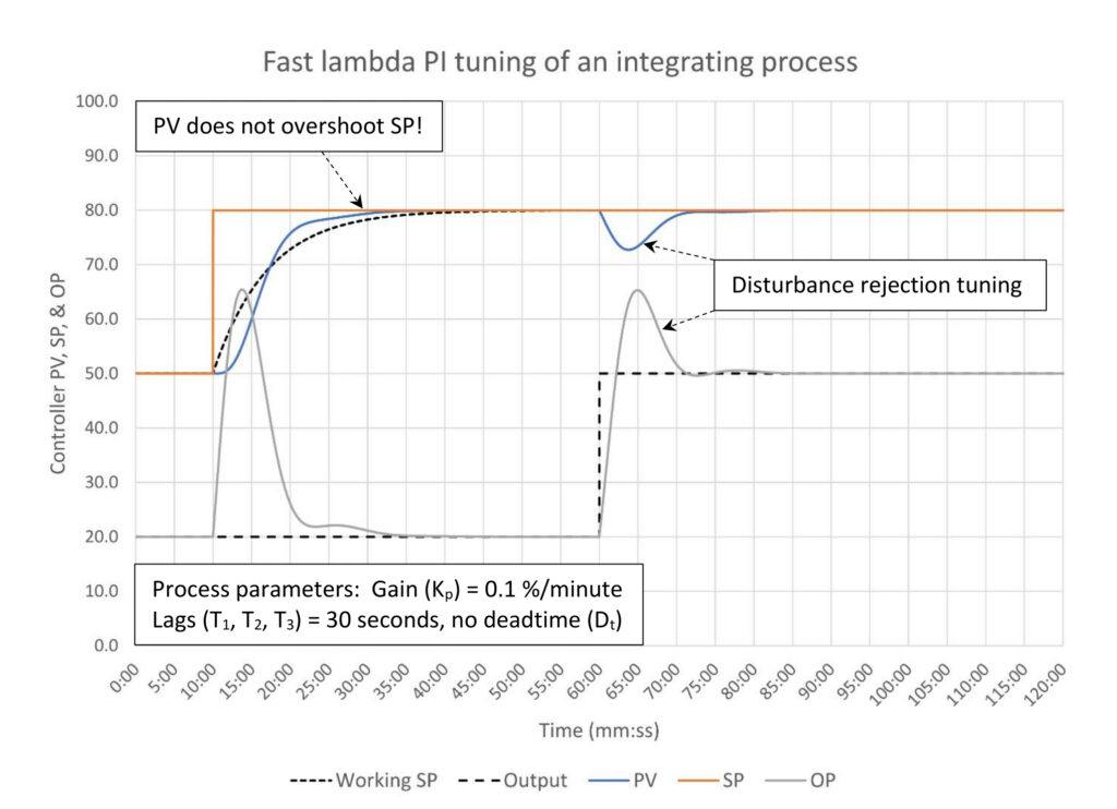
Figure 4 provides a more dramatic example of using a setpoint filter to prevent the process variable from overshooting the setpoint (SP) after the SP is changed. This controller has very aggressive disturbance rejection tuning. Setting the SP filter equal to the controller integral time manages to stop the PV’s rapid rise below the setpoint. The controller output (OP) still moves 45% after the 30% setpoint change, but disturbance rejection tuning implies that we are not that concerned about OP movement. With all that said, in this case setting the SP filter equal to the integral constant provides a good starting point, but based on the slow final approach there may be some room to speed up the SP filter.
Integral only on setpoint change
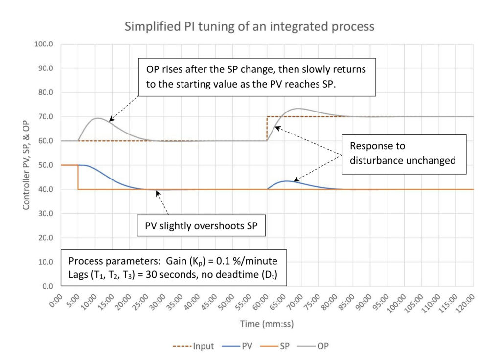
The response of the integral only on setpoint change algorithm as seen in Figure 5 looks very much like the response to a 10-minute setpoint filter (Figure 3). Here, the controller output (OP) peaked at 69.36%, 5 minutes and 45 seconds after the setpoint change. The 10-minute SP filter resulted in an OP peak of 68.73%, 5 minutes and 55 seconds after the SP change. This shouldn’t be too much of a surprise given that the SP filter time constant and the integral constant are about the same. The process variable does get to the new setpoint with just the slightest of overshoots. Otherwise, there is nothing remarkable about the controller response.
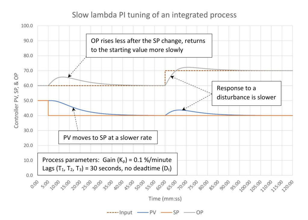
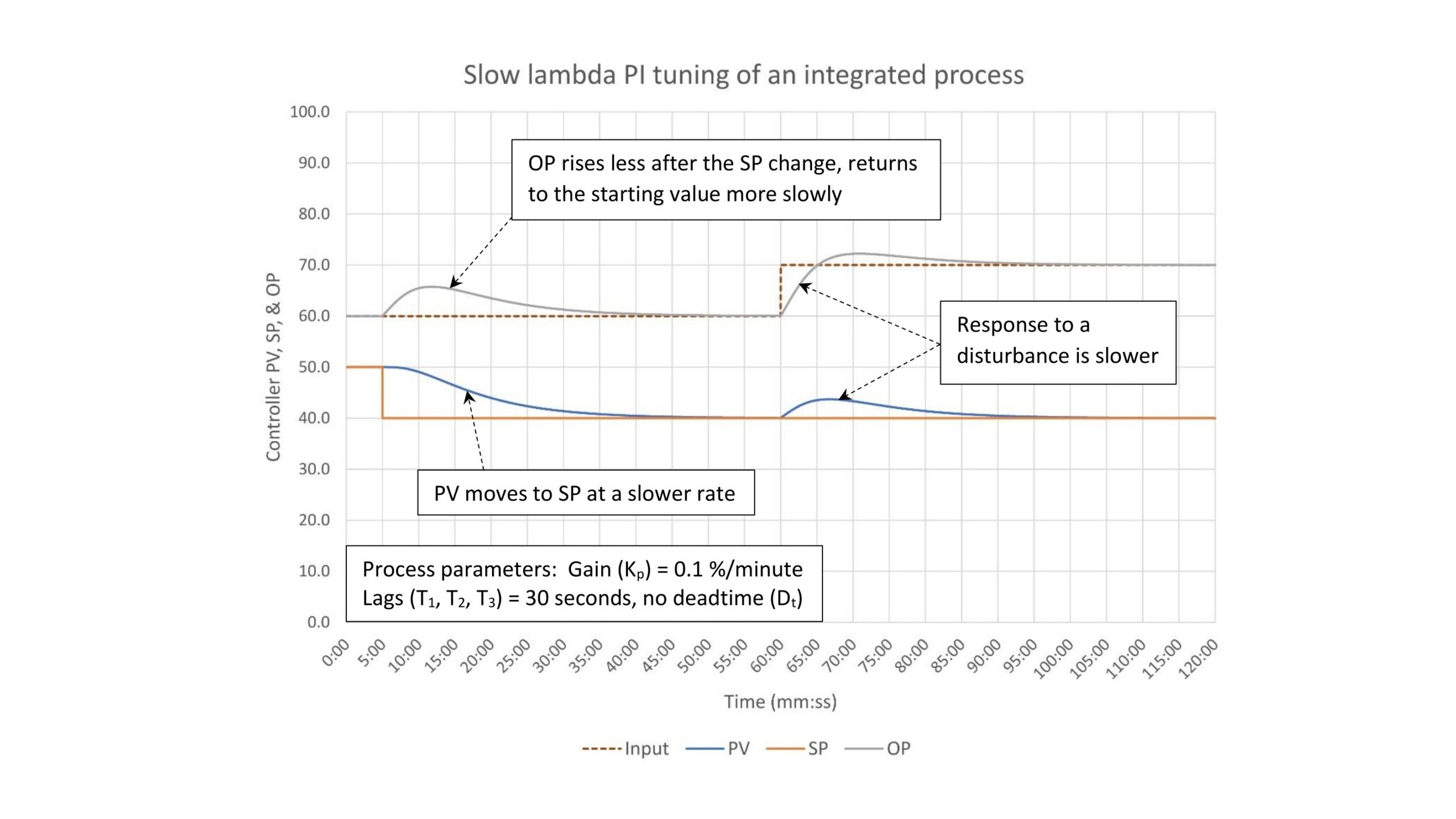
Finally, in Figure 6 we answer the next question: slowing down the integral constant both lowers the controller output peak after a setpoint change (to 65.75% versus 69.36%) and slows down when that peak occurs (6:45 after the SP change versus 5:45). It also slows the controller response to a disturbance.
Advice for integrating processes
As a general rule levels should be set up to use the integral only on setpoint change algorithm, and setpoint ramping should be enabled. Setpoint ramps and filters can be used with the integral only on SP change algorithm. Encourage the operators to use the setpoint ramp whenever they change setpoints. The assumption here is that the vast majority of levels will be tuned for surge control, or close to it.
Should you have an integrating process that must be tuned for disturbance rejection, you have choices. If you need very fast response to setpoint changes, do not use any advanced features. The process variable will overshoot the setpoint and some derivative will be required to suppress oscillations. If process variable overshoot is a problem, use the integral only on setpoint change algorithm or a setpoint filter.
If you are tuning to follow setpoint changes then use a standard PID algorithm. Integral should be very slow, which will minimize process variable overshoot.
Ed Bullerdiek is a retired control engineer with 37 years of process control experience in petroleum refining and oil production. Send comments and questions to [email protected]. Edited by Mark T. Hoske, editor-in-chief, Control Engineering, WTWH Media, [email protected].
Keywords
Proportional-integral-derivative, PID tutorial
Learning objectives
- Understand how setpoint ramps, setpoint filters and the integral only on setpoint change algorithm works with integrating process.
- Know which feature to use to solve how to change a setpoint without upsetting the process or preventing the process variable from overshooting a new setpoint after a change.
- Know that the integral only on setpoint change algorithm is recommended for all level controllers. Other integrating processes should be setup based on process needs.
PID series from Ed Bullerdiek, retired control engineer
PID Spotlight, part 1: Three reasons to tune control loops: Safety, profit, energy efficiency
PID spotlight, part 2: Know these 13 terms, interactions
PID spotlight, part 3: How to select one of four process responses
PID spotlight, part 4: How to balance PID control for a self-limiting process
PID spotlight, part 5: What does good and bad controller tuning look like?
PID spotlight, part 6: Deadtime? How to boost controller performance anyway
PID spotlight, part 7: Open-loop tuning of a self-limiting process
PID spotlight, part 8: Closed-loop tuning for self-limiting processes
PID spotlight, part 9: Heuristic tuning for a self-limiting process (part A on heuristic tuning)
PID spotlight, part 10: Heuristic tuning in a self-limiting process
PID spotlight, part 11: How a PID controller works with an integrating process
PID spotlight, part 12: What does good and bad controller tuning look like?
PID spotlight, part 13: Deadtime: what’s the best that I can do?
PID spotlight, part 14: Open loop tuning of an integrating process
PID spotlight, part 15: Open loop tuning of near integrating processes
PID spotlight, part 16: Closed loop tuning of an integrating process
PID spotlight, part 17: Heuristic tuning of an integrating processes
PID spotlight, part 18: Identifying control valve performance problems
PID spotlight, part 19: PID controller tuning mechanics
PID spotlight, part 20: Tuning with bad valves
PID spotlight, part 21: Noise: Can I tune around it?
PID spotlight, part 22: Can I tune a noisy PID controller?
PID spotlight, part 23: Filtering noise for better PID control
PID spotlight: part 24: How do I tune PID controllers during a new unit startup?
PID spotlight, part 25: Navigating PID controller tuning
PID spotlight, part 26: How fast should I tune my PID controller?
PID spotlight, part 27: Navigating PID controller tuning
PID spotlight, part 28: How well will my PID controller work?
PID spotlight, part 29: How to shape PID controller response – part 1
More on PID and advanced process control from Control Engineering
https://www.controleng.com/control-systems/pid-apc